Tag Archives: Disaster Recovery

Top Architecture Blog Posts of 2023

Post Syndicated from Andrea Courtright original https://aws.amazon.com/blogs/architecture/top-architecture-blog-posts-of-2023/

2023 was a rollercoaster year in tech, and we at the AWS Architecture Blog feel so fortunate to have shared in the excitement. As we move into 2024 and all of the new technologies we could see, we want to take a moment to highlight the brightest stars from 2023.

As always, thanks to our readers and to the many talented and hardworking Solutions Architects and other contributors to our blog.

I give you our 2023 cream of the crop!

#10: Build a serverless retail solution for endless aisle on AWS

In this post, Sandeep and Shashank help retailers and their customers alike in this guided approach to finding inventory that doesn’t live on shelves.

Building endless aisle architecture for order processing

Figure 1. Building endless aisle architecture for order processing

Check it out!

#9: Optimizing data with automated intelligent document processing solutions

Who else dreads wading through large amounts of data in multiple formats? Just me? I didn’t think so. Using Amazon AI/ML and content-reading services, Deependra, Anirudha, Bhajandeep, and Senaka have created a solution that is scalable and cost-effective to help you extract the data you need and store it in a format that works for you.

AI-based intelligent document processing engine

Figure 2: AI-based intelligent document processing engine

Check it out!

#8: Disaster Recovery Solutions with AWS managed services, Part 3: Multi-Site Active/Passive

Disaster recovery posts are always popular, and this post by Brent and Dhruv is no exception. Their creative approach in part 3 of this series is most helpful for customers who have business-critical workloads with higher availability requirements.

Warm standby with managed services

Figure 3. Warm standby with managed services

Check it out!

#7: Simulating Kubernetes-workload AZ failures with AWS Fault Injection Simulator

Continuing with the theme of “when bad things happen,” we have Siva, Elamaran, and Re’s post about preparing for workload failures. If resiliency is a concern (and it really should be), the secret is test, test, TEST.

Architecture flow for Microservices to simulate a realistic failure scenario

Figure 4. Architecture flow for Microservices to simulate a realistic failure scenario

Check it out!

#6: Let’s Architect! Designing event-driven architectures

Luca, Laura, Vittorio, and Zamira weren’t content with their four top-10 spots last year – they’re back with some things you definitely need to know about event-driven architectures.

Let's Architect

Figure 5. Let’s Architect artwork

Check it out!

#5: Use a reusable ETL framework in your AWS lake house architecture

As your lake house increases in size and complexity, you could find yourself facing maintenance challenges, and Ashutosh and Prantik have a solution: frameworks! The reusable ETL template with AWS Glue templates might just save you a headache or three.

Reusable ETL framework architecture

Figure 6. Reusable ETL framework architecture

Check it out!

#4: Invoking asynchronous external APIs with AWS Step Functions

It’s possible that AWS’ menagerie of services doesn’t have everything you need to run your organization. (Possible, but not likely; we have a lot of amazing services.) If you are using third-party APIs, then Jorge, Hossam, and Shirisha’s architecture can help you maintain a secure, reliable, and cost-effective relationship among all involved.

Invoking Asynchronous External APIs architecture

Figure 7. Invoking Asynchronous External APIs architecture

Check it out!

#3: Announcing updates to the AWS Well-Architected Framework

The Well-Architected Framework continues to help AWS customers evaluate their architectures against its six pillars. They are constantly striving for improvement, and Haleh’s diligence in keeping us up to date has not gone unnoticed. Thank you, Haleh!

Well-Architected logo

Figure 8. Well-Architected logo

Check it out!

#2: Let’s Architect! Designing architectures for multi-tenancy

The practically award-winning Let’s Architect! series strikes again! This time, Luca, Laura, Vittorio, and Zamira were joined by Federica to discuss multi-tenancy and why that concept is so crucial for SaaS providers.

Let's Architect

Figure 9. Let’s Architect

Check it out!

And finally…

#1: Understand resiliency patterns and trade-offs to architect efficiently in the cloud

Haresh, Lewis, and Bonnie revamped this 2022 post into a masterpiece that completely stole our readers’ hearts and is among the top posts we’ve ever made!

Resilience patterns and trade-offs

Figure 10. Resilience patterns and trade-offs

Check it out!

Bonus! Three older special mentions

These three posts were published before 2023, but we think they deserve another round of applause because you, our readers, keep coming back to them.

Thanks again to everyone for their contributions during a wild year. We hope you’re looking forward to the rest of 2024 as much as we are!

Disaster Recovery Solutions with AWS-Managed Services, Part 3: Multi-Site Active/Passive

Post Syndicated from Brent Kim original https://aws.amazon.com/blogs/architecture/disaster-recovery-solutions-with-aws-managed-services-part-3-multi-site-active-passive/

Welcome to the third post of a multi-part series that addresses disaster recovery (DR) strategies with the use of AWS-managed services to align with customer requirements of performance, cost, and compliance. In part two of this series, we introduced a DR concept that utilizes managed services through a backup and restore strategy with multiple Regions. The post also introduces a multi-site active/passive approach.

The multi-site active/passive approach is best for customers who have business-critical workloads with higher availability requirements over other active/passive environments. A warm-standby strategy (as in Figure 1) is more costly than other active/passive strategies, but provides good protection from downtime and data loss outside of an active/active (A/A) environment.

Warm standby

Figure 1. Warm standby

Implementing the multi-site active/passive strategy

By replicating across multiple Availability Zones in same Region, your workloads become resilient to the failure of an entire data center. Using multiple Regions provides the most resilient option to deploy workloads, which safeguards against the risk of failure of multiple data centers.

Let’s explore an application that processes payment transactions and is modernized to utilize managed services in the AWS Cloud, as in Figure 2.

Warm standby with managed services

Figure 2. Warm standby with managed services

Let’s cover each of the components of this application, as well as how managed services behave in a multisite environment.

1. Amazon Route53 – Active/Passive Failover: This configuration consists of primary resources to be available, and secondary resources on standby in the case of failure of the primary environment. You would just need to create the records and specify failover for the routing policy. When responding to queries, Amazon Route 53 includes only the healthy primary resources. If the primary record configured in the Route 53 health check shows as unhealthy, Route 53 responds to DNS queries using the secondary record.

2. Amazon EKS control plane: Amazon Elastic Kubernetes Service (Amazon EKS) control plane nodes run in an account managed by AWS. Each EKS cluster control plane is single-tenant and unique, and runs on its own set of Amazon Elastic Compute Cloud (Amazon EC2) instances. Amazon EKS is also a Regional service, so each cluster is confined to the Region where it is deployed, with each cluster being a standalone entity.

3. Amazon EKS data plane: Operating highly available and resilient applications requires a highly available and resilient data plane. It’s best practice to create worker nodes using Amazon EC2 Auto Scaling groups instead of creating individual Amazon EC2 instances and joining them to the cluster.

Figure 2 shows three nodes in the primary Region while there will only be a single node in the secondary. In case of failover, the data plane scales up to meet the workload requirements. This strategy deploys a functional stack to the secondary Region to test Region readiness before failover. You can use Velero with Portworx to manage snapshots of persistent volumes. These snapshots can be stored in an Amazon Simple Storage Service (Amazon S3) bucket in the primary Region, which is replicated to an Amazon S3 bucket in another Region using Amazon S3 cross-Region replication.

During an outage in the primary Region, Velero restores volumes from the latest snapshots in the standby cluster.

4. Amazon OpenSearch Service: With cross-cluster replication in Amazon OpenSearch Service, you can replicate indexes, mappings, and metadata from one OpenSearch Service domain to another. The domain follows an active-passive replication model where the follower index (where the data is replicated) pulls data from the leader index. Using cross-cluster replication helps to ensure recovery from disaster events and allows you to replicate data across geographically distant data centers to reduce latency.

Cross-cluster replication is available on domains running Elasticsearch 7.10 or OpenSearch 1.1 or later. Full documentation for cross-cluster replication is available in the OpenSearch documentation.

If you are using any versions prior to Elasticsearch 7.10 or OpenSearch 1.1, refer to part two of our blog series for guidance on using APIs for cross-Region replication.

5. Amazon RDS for PostgreSQL: One of the managed service offerings of Amazon Relational Database Service (Amazon RDS) for PostgreSQL is cross-Region read replicas. Cross-Region read replicas enable you to have a DR solution scaling read database workloads, and cross-Region migration.

Amazon RDS for PostgreSQL supports the ability to create read replicas of a source database (DB). Amazon RDS uses an asynchronous replication method of the DB engine to update the read replica whenever there is a change made on the source DB instance. Although read replicas operate as a DB instance that allows only read-only connections, they can be used to implement a DR solution for your production DB environment. If the source DB instance fails, you can promote your Read Replica to a standalone source server.

Using a cross-Region read replica helps ensure that you get back up and running if you experience a Regional availability issue. For more information on PostgreSQL cross-Region read replicas, visit the Best Practices for Amazon RDS for PostgreSQL Cross-Region Read Replicas blog post.

6. Amazon ElastiCache: AWS provides a native solution called Global Datastore that enables cross-Region replication. By using the Global Datastore for Redis feature, you can work with fully managed, fast, reliable, and secure replication across AWS Regions. This feature helps create cross-Region read replica clusters for ElastiCache for Redis to enable low-latency reads and DR across AWS Regions. Each global datastore is a collection of one or more clusters that replicate to one another. When you create a global datastore in Amazon ElastiCache, ElastiCache for Redis automatically replicates your data from the primary cluster to the secondary cluster. ElastiCache then sets up and manages automatic, asynchronous replication of data between the two clusters.

7. Amazon Redshift: With Amazon Redshift, there are only two ways of deploying a true DR approach: backup and restore, and an (A/A) solution. We’ll use the A/A solution as this provides a better recovery time objective (RTO) for the overall approach. The recovery point objective (RPO) is dependent upon the configured schedule of AWS Lambda functions. The application within the primary Region sends data to both Amazon Simple Notification Service (Amazon SNS) and Amazon S3, and the data is distributed to the Redshift clusters in both Regions through Lambda functions.

Amazon EKS uploads data to an Amazon S3 bucket and publishes a message to an Amazon SNS topic with a reference to the stored S3 object. S3 acts as an intermediate data store for messages beyond the maximum output limit of Amazon SNS. Amazon SNS is configured with primary and secondary Region Amazon Simple Queue Service (Amazon SQS) endpoint subscriptions. Amazon SNS supports the cross-Region delivery of notifications to Amazon SQS queues. Lambda functions deployed in the primary and secondary Region are used to poll the Amazon SQS queue in respective Regions to read the message. The Lambda functions then use the Amazon SQS Extended Client Library for Java to retrieve the Amazon S3 object referenced in the message. Once the Amazon S3 object is retrieved, the Lambda functions upload the data into Amazon Redshift.

For more on how to coordinate large messages across accounts and Regions with Amazon SNS and Amazon SQS, explore the Coordinating Large Messages Across Accounts and Regions with Amazon SNS and SQS blog post.

Conclusion

This active/passive approach covers how you can build a creative DR solution using a mix of native and non-native cross-Region replication methods. By using managed services, this strategy becomes simpler through automation of service updates, deployment using Infrastructure as a Code (IaaC), and general management of the two environments.

Related information

Want to learn more? Explore the following resources within this series and beyond!

Understand resiliency patterns and trade-offs to architect efficiently in the cloud

Post Syndicated from Haresh Nandwani original https://aws.amazon.com/blogs/architecture/understand-resiliency-patterns-and-trade-offs-to-architect-efficiently-in-the-cloud/

This post was originally published in June 2022 and is now updated with more information on efficiently architecting resilient patterns in the cloud.


Architecting workloads for resilience on the cloud often need to evaluate multiple factors before they can decide the most optimal architecture for their workloads.

Example Corp has multiple applications with varying criticality, and each of their applications have different needs in terms of resiliency, complexity, and cost. They have many choices to architect their workloads for resiliency and cost, but which option suits their needs best? What should they consider when choosing the patterns most appropriate for the needs of their applications?

To help answer these questions, we’ll discuss the five resilience patterns in Figure 1 and the trade-offs to consider when implementing them: 1) design complexity, 2) cost to implement, 3) operational effort, 4) effort to secure, and 5) environmental impact. This will help you achieve varying levels of resiliency and make decisions about the most appropriate architecture for your needs. Our intent is to provide a high-level approach to structure conversations on trade-offs associated with each of these patterns. For a deeper dive on each pattern, please navigate to the Further reading section at the end of this post.

Note: these patterns are not mutually exclusive; you may decide to implement a combination of one of more patterns.

Resilience patterns and trade-offs

Figure 1. Resilience patterns and trade-offs

What is resiliency? Why does it matter?

The AWS Well-Architected Framework defines resilience as having “the capability to recover when stressed by load (more requests for service), attacks (either accidental through a bug, or deliberate through intention), and failure of any component in the workload’s components.”

To meet your business’ resilience requirements, consider the following core factors as you design your workloads:

  • Design complexity – An increase in system complexity typically increases the emergent behaviors of that system. Each individual workload component has to be resilient, and you’ll need to eliminate single points of failure across people, process, and technology elements. Customers should consider their resilience requirements and decide if increasing system complexity is an effective approach, or if keeping the system simple and using a disaster recovery (DR) plan is be more appropriate.
  • Cost to implement – Costs often significantly increase when you implement higher resilience because there are new software and infrastructure components to operate. It’s important for such costs to be offset by the potential costs of future loss.
  • Operational effort – Deploying and supporting highly resilient systems requires complex operational processes and advanced technical skills. For example, customers might need to improve their operational processes using the Operational Readiness Review (ORR) approach. Before you decide to implement higher resilience, evaluate your operational competency to confirm you have the required level of process maturity and skillsets.
  • Effort to secure – Security complexity is less directly correlated with resilience. However, there are generally more components to secure for highly resilient systems. Using security best practices for cloud deployments can achieve security objectives without adding significant complexity even with a higher deployment footprint.
  • Environmental impact – An increased deployment footprint for resilient systems may increase your consumption of cloud resources. However, you can use trade-offs, like approximate computing and deliberately implementing slower response times to reduce resource consumption. The AWS Well-Architected Sustainability Pillar describes these patterns and provides guidance on sustainability best practices.

Pattern 1 (P1): Multi-AZ

P1 is a cloud-based architecture pattern (Figure 2) that introduces Availability Zones (AZs) into your architecture to increase your system’s resilience. The P1 pattern uses a Multi-AZ architecture where applications operate in multiple AZs within a single AWS Region. This allows your application to withstand AZ-level impacts.

As shown in Figure 2, Example Corp deploys their internal employee applications using the P1 pattern. These applications are low business impact and therefore have lower requirements for resiliency.

Example Corp deploys their low-business-impact applications as a single Amazon Elastic Compute Cloud (Amazon EC2) instance managed by an Auto Scaling group. Amazon EC2 uses health checks to automatically detect faults. If an AZ fails, Amazon EC2 prompts an Amazon EC2 Auto Scaling group to recreate their application in another unaffected AZ.

Multi-AZ deployment pattern (P1)

Figure 2. Multi-AZ deployment pattern (P1)

Trade-offs

P1 is low in several categories and mitigates a disruption to the AZ hosting the application, but this comes at the expense of application recovery. If an AZ is down, it will disrupt end users’ access to the application while the new resources are being re-provisioned in a new AZ. This is known as bi-modal behavior.

Pattern 2 (P2): Multi-AZ with static stability

P2 uses multiple instances across multiple AZs within a Region to increase resilience. The pattern uses static stability to prevent bimodal behavior. Statically stable systems remain stable and operate in one mode, irrespective of changes to their operating environment. A key benefit of a statically stable system on AWS is it reduces complexity of recovery during a disruption thanks to pre-provisioned resource capacity. Any resources needed to maintain operations during a disruption, such as the loss of resources in an AZ, already exist and AWS service control planes do not need to be available for recovery to be successful. To learn more about static stability, data planes and control planes read the builder’s library article Static stability using Availability Zones.

As shown in Figure 3, Example Corp has a customer-facing website that has a lower tolerance for downtime. Any time the website is down, it could result in lost revenue. Because of this, the website requires two EC2 instances that are provisioned within two AZs. Using health checks, when the AZ becomes impaired, the website continues to operate as the Elastic Load Balancer diverts traffic away from the impacted AZ. For more on using health checks, see the Implementing health checks article in The Amazon Builder’s Library.

Multi-AZ with static stability pattern (P2)

Figure 3. Multi-AZ with static stability pattern (P2)

Trade-offs

P2 mitigates an AZ disruption without downtime to application clients but must be weighed against cost concerns. P1 is less expensive from an infrastructure cost perspective, as it provisions less compute capacity and relies on launching new instances in case of a failure. However, P1’s bimodal behavior can affect your customers during large-scale events.

Implementing P2 requires your application to support distributed operation across multiple instances. If your application can support this pattern, you can deploy your workload to all available AZs (usually 3 or more) across the Region. This will reduce costs associated with over-provisioning because you only have to provision 150% of your capacity across three AZs compared with the 200% in two AZs (as mentioned in our earlier example).

Pattern 3 (P3): Application portfolio distribution

P3 uses a Multi-Region pattern to increase functional resilience, as demonstrated in Figure 4. It distributes different critical applications in multiple Regions.

Example Corp provides banking services, like credit balance checks, to consumers on multiple digital channels. These services are available to consumers via a mobile application, contact center, and web-based applications. Each digital channel is deployed to a separate Region, which mitigates against a regional service disruption.

For example, a Region with the customers’ mobile application may have a disruption that causes the mobile app to be unavailable, but customers can still access banking services via online banking deployed in an alternate Region. Regional service disruptions are rare, but implementing a pattern like this ensures your users retain access to business-critical services during disruptions.

Application portfolio distribution pattern (P3)

Figure 4. Application portfolio distribution pattern (P3)

Trade-offs

P3 mitigates the possibility of a regional service disruption impacting a multitude of systems at the same time. Operating an application portfolio that spans multiple Regions requires significant operational planning and management. Isolated functional elements may depend on common downstream systems and data sources that are deployed in a single Region. Therefore, Region-wide events may still cause disruption, but the impact surface area should be reduced.

Pattern 4 (P4): Multi-AZ deployment (multi-Region DR)

Example Corp operates several business-critical services that have a very low tolerance for disruption, such as the ability for consumers to make bank payments. Example Corp reviewed the four common patterns for DR (as defined in Disaster Recovery of Workloads on AWS: Recovery in the Cloud) and decided to use the following sub-patterns for their multi-Region applications:

  • Pilot Light – This pattern works for applications that require RTO/RPO of 10s of minutes. Data is actively replicated and application infrastructure is pre-provisioned in the DR Region. Cost optimization is a key driver here, as the application infrastructure is kept switched-off and only switched-on during the restore event.
  • Warm Standby – This pattern improves restore times significantly compared with pilot light by keeping your applications running in the DR Region but with a reduced capacity. Application infrastructure will be scaled up during a DR event, but this can typically be automated with minimal manual effort. This pattern can achieve RTO/RPO of minutes if implemented correctly.

Trade-offs

P4 mitigates a disruption to a regional service while reducing mitigation costs. Regional DR patterns increase deployment complexity as infrastructure changes need to be synchronized across Regions. Testing resilience is also significantly more complex and include simulating regional disruptions. Using Infrastructure as Code to automate deployments can help alleviate these issues.

Pattern 5 (P5): Multi-Region active-active

Example Corp’s core banking and Customer Relationship Management applications have zero tolerance for disruption. They use the P5 pattern for deploying these applications because it has an RTO of real-time and an RPO of near-zero data loss. They run their workload simultaneously in multiple Regions, allowing them to serve traffic from all Regions simultaneously. This pattern not only mitigates against regional disruptions but also addresses their zero tolerance requirements (Figure 5).

Multi-Region active-active pattern (P5)

Figure 5. Multi-Region active-active pattern (P5)

Trade-offs

P5 mitigates the disruption of a regional service, and invests additional costs and complexity to deliver a RTO of near zero. Multi-active deployments are generally complex, as they include multiple applications that collaborate to deliver required business services. If you implement this pattern, you’ll need to consider the fact that you’re introducing asynchronous replication for data across Regions and the impact that has on data consistency.

Operating this pattern requires a very high level of process maturity, so we recommend customers gradually build towards this pattern by starting with the deployment patterns described earlier.

Conclusion

In this blog post, we introduced five resilience patterns and trade-offs to consider when implementing them. In an effort to help you find the most efficient architecture for your use case, we demonstrated how Example Corp evaluated these options and how they applied them to their business needs.

Further reading

Looking for more architecture content?

AWS Architecture Center provides reference architecture diagrams, vetted architecture solutions, Well-Architected best practices, patterns, icons, and more!

How to use regional SAML endpoints for failover

Post Syndicated from Jonathan VanKim original https://aws.amazon.com/blogs/security/how-to-use-regional-saml-endpoints-for-failover/

Many Amazon Web Services (AWS) customers choose to use federation with SAML 2.0 in order to use their existing identity provider (IdP) and avoid managing multiple sources of identities. Some customers have previously configured federation by using AWS Identity and Access Management (IAM) with the endpoint signin.aws.amazon.com. Although this endpoint is highly available, it is hosted in a single AWS Region, us-east-1. This blog post provides recommendations that can improve resiliency for customers that use IAM federation, in the unlikely event of disrupted availability of one of the regional endpoints. We will show you how to use multiple SAML sign-in endpoints in your configuration and how to switch between these endpoints for failover.

How to configure federation with multi-Region SAML endpoints

AWS Sign-In allows users to log in into the AWS Management Console. With SAML 2.0 federation, your IdP portal generates a SAML assertion and redirects the client browser to an AWS sign-in endpoint, by default signin.aws.amazon.com/saml. To improve federation resiliency, we recommend that you configure your IdP and AWS federation to support multiple SAML sign-in endpoints, which requires configuration changes for both your IdP and AWS. If you have only one endpoint configured, you won’t be able to log in to AWS by using federation in the unlikely event that the endpoint becomes unavailable.

Let’s take a look at the Region code SAML sign-in endpoints in the AWS General Reference. The table in the documentation shows AWS regional endpoints globally. The format of the endpoint URL is as follows, where <region-code> is the AWS Region of the endpoint: https://<region-code>.signin.aws.amazon.com/saml

All regional endpoints have a region-code value in the DNS name, except for us-east-1. The endpoint for us-east-1 is signin.aws.amazon.com—this endpoint does not contain a Region code and is not a global endpoint. AWS documentation has been updated to reference SAML sign-in endpoints.

In the next two sections of this post, Configure your IdP and Configure IAM roles, I’ll walk through the steps that are required to configure additional resilience for your federation setup.

Important: You must do these steps before an unexpected unavailability of a SAML sign-in endpoint.

Configure your IdP

You will need to configure your IdP and specify which AWS SAML sign-in endpoint to connect to.

To configure your IdP

  1. If you are setting up a new configuration for AWS federation, your IdP will generate a metadata XML configuration file. Keep track of this file, because you will need it when you configure the AWS portion later.
  2. Register the AWS service provider (SP) with your IdP by using a regional SAML sign-in endpoint. If your IdP allows you to import the AWS metadata XML configuration file, you can find these files available for the public, GovCloud, and China Regions.
  3. If you are manually setting the Assertion Consumer Service (ACS) URL, we recommend that you pick the endpoint in the same Region where you have AWS operations.
  4. In SAML 2.0, RelayState is an optional parameter that identifies a specified destination URL that your users will access after signing in. When you set the ACS value, configure the corresponding RelayState to be in the same Region as the ACS. This keeps the Region configurations consistent for both ACS and RelayState. Following is the format of a Region-specific console URL.

    https://<region-code>.console.aws.amazon.com/

    For more information, refer to your IdP’s documentation on setting up the ACS and RelayState.

Configure IAM roles

Next, you will need to configure IAM roles’ trust policies for all federated human access roles with a list of all the regional AWS Sign-In endpoints that are necessary for federation resiliency. We recommend that your trust policy contains all Regions where you operate. If you operate in only one Region, you can get the same resiliency benefits by configuring an additional endpoint. For example, if you operate only in us-east-1, configure a second endpoint, such as us-west-2. Even if you have no workloads in that Region, you can switch your IdP to us-west-2 for failover. You can log in through AWS federation by using the us-west-2 SAML sign-in endpoint and access your us-east-1 AWS resources.

To configure IAM roles

  1. Log in to the AWS Management Console with credentials to administer IAM. If this is your first time creating the identity provider trust in AWS, follow the steps in Creating IAM SAML identity providers to create the identity providers.
  2. Next, create or update IAM roles for federated access. For each IAM role, update the trust policy that lists the regional SAML sign-in endpoints. Include at least two for increased resiliency.

    The following example is a role trust policy that allows the role to be assumed by a SAML provider coming from any of the four US Regions.

    {
        "Version": "2012-10-17",
        "Statement": [
            {
                "Effect": "Allow",
                "Principal": {
                    "Federated": "arn:aws:iam:::saml-provider/IdP"
                },
                "Action": "sts:AssumeRoleWithSAML",
                "Condition": {
                    "StringEquals": {
                        "SAML:aud": [
                            "https://us-east-2.signin.aws.amazon.com/saml",
                            "https://us-west-1.signin.aws.amazon.com/saml",
                            "https://us-west-2.signin.aws.amazon.com/saml",
                            "https://signin.aws.amazon.com/saml"
                        ]
                    }
                }
            }
        ]
    }

  3. When you use a regional SAML sign-in endpoint, the corresponding regional AWS Security Token Service (AWS STS) endpoint is also used when you assume an IAM role. If you are using service control policies (SCP) in AWS Organizations, check that there are no SCPs denying the regional AWS STS service. This will prevent the federated principal from being able to obtain an AWS STS token.

Switch regional SAML sign-in endpoints

In the event that the regional SAML sign-in endpoint your ACS is configured to use becomes unavailable, you can reconfigure your IdP to point to another regional SAML sign-in endpoint. After you’ve configured your IdP and IAM role trust policies as described in the previous two sections, you’re ready to change to a different regional SAML sign-in endpoint. The following high-level steps provide guidance on switching the regional SAML sign-in endpoint.

To switch regional SAML sign-in endpoints

  1. Change the configuration in the IdP to point to a different endpoint by changing the value for the ACS.
  2. Change the configuration for the RelayState value to match the Region of the ACS.
  3. Log in with your federated identity. In the browser, you should see the new ACS URL when you are prompted to choose an IAM role.
    Figure 1: New ACS URL

    Figure 1: New ACS URL

The steps to reconfigure the ACS and RelayState will be different for each IdP. Refer to the vendor’s IdP documentation for more information.

Conclusion

In this post, you learned how to configure multiple regional SAML sign-in endpoints as a best practice to further increase resiliency for federated access into your AWS environment. Check out the updates to the documentation for AWS Sign-In endpoints to help you choose the right configuration for your use case. Additionally, AWS has updated the metadata XML configuration for the public, GovCloud, and China AWS Regions to include all sign-in endpoints.

The simplest way to get started with SAML federation is to use AWS Single Sign-On (AWS SSO). AWS SSO helps manage your permissions across all of your AWS accounts in AWS Organizations.

If you have any questions, please post them in the Security Identity and Compliance re:Post topic or reach out to AWS Support.

Want more AWS Security news? Follow us on Twitter.

Jonathan VanKim

Jonathan VanKim

Jonathan VanKim is a Sr. Solutions Architect who specializes in Security and Identity for AWS. In 2014, he started working AWS Proserve and transitioned to SA 4 years later. His AWS career has been focused on helping customers of all sizes build secure AWS architectures. He enjoys snowboarding, wakesurfing, travelling, and experimental cooking.

Arynn Crow

Arynn Crow

Arynn Crow is a Manager of Product Management for AWS Identity. Arynn started at Amazon in 2012, trying out many different roles over the years before finding her happy place in security and identity in 2017. Arynn now leads the product team responsible for developing user authentication services at AWS.

Disaster recovery with AWS managed services, Part 2: Multi-Region/backup and restore

Post Syndicated from Dhruv Bakshi original https://aws.amazon.com/blogs/architecture/disaster-recovery-with-aws-managed-services-part-ii-multi-region-backup-and-restore/

In part I of this series, we introduced a disaster recovery (DR) concept that uses managed services through a single AWS Region strategy. In part two, we introduce a multi-Region backup and restore approach. With this approach, you can deploy a DR solution in multiple Regions, but it will be associated with longer RPO/RTO. Using a backup and restore strategy will safeguard applications and data against large-scale events as a cost-effective solution, but will result in longer downtimes and greater loss of data in the event of a disaster as compared to other strategies as shown in Figure 1.

DR Strategies

Figure 1. DR Strategies

Implementing the multi-Region/backup and restore strategy

Using multiple Regions ensures resiliency in the most serious, widespread outages. A secondary Region protects workloads against being unable to run within a given Region, because they are wide and geographically dispersed.

Architecture overview

The application diagram presented in Figures 2.1 and 2.2 refers to an application that processes payment transactions, which was modernized to utilize managed services in the AWS Cloud. In this post, we’ll show you which AWS services it uses and how they work to maintain multi-Region/backup and restore strategy.

These figures show how to successfully implement the backup and restore strategy and successfully fail over your workload. The following sections list the components of the example application presented in the figures, which works as follows:

Multi-Region backup

Figure 2.1. Multi-Region backup

Multi-Region restore

Figure 2.2. Multi-Region restore

Route 53

Route 53 health checks monitor the health and performance of your web applications, web servers, and other resources. Health checks are necessary for configuring DNS failover within Route 53. Once an application or resource becomes unhealthy, you’ll need to initiate a manual failover process to create resources in the secondary Region. In our architecture, we use CloudWatch alarms to automate notifications of changes in health status.

Please check out the Creating Disaster Recovery Mechanisms Using Amazon Route 53 blog post for additional DR mechanisms using Amazon Route 53.

Amazon EKS control plane

Amazon Elastic Kubernetes Service (Amazon EKS) automatically scales control plane instances based on load, automatically detects and replaces unhealthy control plane instances, and restarts them across the Availability Zones within the Region as needed. Because on-demand clusters are provisioned in the secondary Region, AWS also manages the control plane the same way.

Amazon EKS data plane

It is a best practice to create worker nodes using Amazon Elastic Compute Cloud (Amazon EC2) Auto Scaling groups instead of creating individual EC2 instances and joining them to the cluster. This is because Amazon EC2 Auto Scaling groups automatically replace any terminated or failed nodes, which ensures that the cluster always has the capacity to run your workload.

The Amazon EKS control plane and data plane will be created on demand in the secondary Region during an outage via Infrastructure-as-a-Code (IaaC) such as AWS CloudFormation, Terraform, etc. You should pre-stage all networking requirements like virtual private cloud (VPC), subnets, route tables, gateways and deploy the Amazon EKS cluster during an outage in the primary Region.

As shown in the Backup and restore your Amazon EKS cluster resources using Velero blog post, you may use a third-party tool like Velero for managing snapshots of persistent volumes. These snapshots can be stored in an Amazon Simple Storage Service (Amazon S3) bucket in the primary Region, which will be replicated to an S3 bucket in another Region via cross-Region replication.

During an outage in the primary Region, you can use the tool in the secondary Region to restore volumes from snapshots in the standby cluster.

OpenSearch Service

For domains running Amazon OpenSearch Service, OpenSearch Service takes hourly automated snapshots and retains up to 336 for 14 days. These snapshots can only be used for cluster recovery within the same Region as the primary OpenSearch cluster.

You can use OpenSearch APIs to create a manual snapshot of an OpenSearch cluster, which can be stored in a registered repository like Amazon S3. You can do this manually or create a scheduled Lambda function based on their RPO, which prompts creation of a manual snapshot that will be stored in an S3 bucket. Amazon S3 cross-Region replication will then automatically and asynchronously copy objects across S3 buckets.

You can restore OpenSearch Service clusters by creating the cluster on demand via CloudFormation and using OpenSearch APIs to restore the snapshot from an S3 bucket.

Amazon RDS Postgres

Amazon Relational Database Service (Amazon RDS) can copy continuous backups cross-Region. You can configure your Amazon RDS database instance to replicate snapshots and transaction logs to a destination Region of your choice.

If a continuous backup rule also specifies a cross-account or cross-Region copy, AWS Backup takes a snapshot of the continuous backup, copies that snapshot to the destination vault, and then deletes the source snapshot. For continuous backup of Amazon RDS, AWS Backup creates a snapshot every 24 hours and stores transaction logs every 5 minutes in-Region. The Backup Frequency setting only applies to cross-Region backups of these continuous backups. Backup Frequency determines how often AWS Backup:

  • Creates a snapshot at that point in time from the existing snapshot plus all transaction logs up to that point
  • Copies snapshots to the other Region(s)
  • Deletes snapshots (because it only was created to be copied)

For more information, refer to the Point-in-time recovery and continuous backup for Amazon RDS with AWS Backup blog post.

ElastiCache

You can export and import backup and copy API calls for Amazon ElastiCache to develop a snapshot and restore strategy in a secondary Region. You can either prompt a manual backup and copy of that backup to S3 bucket or create a pair of Lambda functions to run at a schedule to meet the RPO requirements. The Lambda functions will prompt a manual backup, which creates a .rdb to an S3 bucket. Amazon S3 cross-Region replication will then handle asynchronous copy of the backup to an S3 bucket in a secondary Region.

You can use CloudFormation to create an ElastiCache cluster on demand and use CloudFormation properties such as SnapshotArns and SnapshotName to point to the desired ElastiCache backup stored in Amazon S3 to seed the cluster in the secondary Region.

Amazon Redshift

Amazon Redshift takes automatic, incremental snapshots of your data periodically and saves them to Amazon S3. Additionally, you can take manual snapshots of your data whenever you want.

To precisely control when snapshots are taken, you can create a snapshot schedule and attach it to one or more clusters. You can also configure cross-Region snapshot copy, which will automatically copy all your automated and manual snapshots to another Region.

During an outage, you can create the Amazon Redshift cluster on demand via CloudFormation and use CloudFormation properties such as SnapshotIdentifier to restore the new cluster from that snapshot.

Note: You can add an additional layer of protection to your backups through AWS Backup Vault Lock, S3 Object Lock, and Encrypted Backups.

Conclusion

With greater adoption of managed services within the cloud, there is a need to think of creative ways to implement a cost-effective DR solution. This backup and restore approach offered in this post will lower costs through more lenient RPO/RTO requirements, while providing a solution to utilize AWS managed services.

In the next post, we will discuss a multi-Region active/active strategy for the same application stack illustrated in this post.

Other posts in this series

Related information

Looking for more architecture content? AWS Architecture Center provides reference architecture diagrams, vetted architecture solutions, Well-Architected best practices, patterns, icons, and more!

Minimizing Dependencies in a Disaster Recovery Plan

Post Syndicated from Randy DeFauw original https://aws.amazon.com/blogs/architecture/minimizing-dependencies-in-a-disaster-recovery-plan/

The Availability and Beyond whitepaper discusses the concept of static stability for improving resilience. What does static stability mean with regard to a multi-Region disaster recovery (DR) plan? What if the very tools that we rely on for failover are themselves impacted by a DR event?

In this post, you’ll learn how to reduce dependencies in your DR plan and manually control failover even if critical AWS services are disrupted. As a bonus, you’ll see how to use service control policies (SCPs) to help simulate a Regional outage, so that you can test failover scenarios more realistically.

Failover plan dependencies and considerations

Let’s dig into the DR scenario in more detail. Using Amazon Route 53 for Regional failover routing is a common pattern for DR events. In the simplest case, we’ve deployed an application in a primary Region and a backup Region. We have a Route 53 DNS record set with records for both Regions, and all traffic goes to the primary Region. In an event that triggers our DR plan, we manually or automatically switch the DNS records to direct all traffic to the backup Region.

Relying on an automated health check to control Regional failover can be tricky. A health check might not be perfectly reliable if a Region is experiencing some type of degradation. Often, we prefer to initiate our DR plan manually, which then initiates with automation.

What are the dependencies that we’ve baked into this failover plan? First, Route 53, our DNS service, has to be available. It must continue to serve DNS queries, and we have to be able to change DNS records manually. Second, if we do not have a full set of resources already deployed in the backup Region, we must be able to deploy resources into it.

Both dependencies might violate static stability, because we are relying on resources in our DR plan that might be affected by the outage we’re seeing. Ideally, we don’t want to depend on other services running so we can failover and continue to serve our own traffic. How do we reduce additional dependencies?

Static stability

Let’s look at our first dependency on Route 53 – control planes and data planes. Briefly, a control plane is used to configure resources, and the data plane delivers services (see Understanding Availability Needs for a more complete definition.)

The Route 53 data plane, which responds to DNS queries, is highly resilient across Regions. We can safely rely on it during the failure of any single Region. But let’s assume that for some reason we are not able to call on the Route 53 control plane.

Amazon Route 53 Application Recovery Controller (Route 53 ARC) was built to handle this scenario. It provisions a Route 53 health check that we can manually control with a Route 53 ARC routing control, and is a data plane operation. The Route 53 ARC data plane is highly resilient, using a cluster of five Regional endpoints. You can revise the health check if three of the five Regions are available.

Figure 1. Simple Regional failover scenario using Route 53 Application Recovery Controller

Figure 1. Simple Regional failover scenario using Route 53 Application Recovery Controller

The second dependency, being able to deploy resources into the second Region, is not a concern if we run a fully scaled-out set of resources. We must make sure that our deployment mechanism doesn’t rely only on the primary Region. Most AWS services have Regional control planes, so this isn’t an issue.

The AWS Identity and Access Management (IAM) data plane is highly available in each Region, so you can authorize the creation of new resources as long as you’ve already defined the roles. Note: If you use federated authentication through an identity provider, you should test that the IdP does not itself have a dependency on another Region.

Testing your disaster recovery plan

Once we’ve identified our dependencies, we need to decide how to simulate a disaster scenario. Two mechanisms you can use for this are network access control lists (NACLs) and SCPs. The first one enables us to restrict network traffic to our service endpoints. However, the second allows defining policies that specify the maximum permissions for the target accounts. It also allows us to simulate a Route 53 or IAM control plane outage by restricting access to the service.

For the end-to-end DR simulation, we’ve published an AWS samples repository on GitHub that you can use to deploy. This evaluates Route 53 ARC capabilities if both Route 53 and IAM control planes aren’t accessible.

By deploying test applications across us-east-1 and us-west-1 AWS Regions, we can simulate a real-world scenario that determines the business continuity impact, failover timing, and procedures required for successful failover with unavailable control planes.

Figure 2. Simulating Regional failover using service control policies

Figure 2. Simulating Regional failover using service control policies

Before you conduct the test outlined in our scenario, we strongly recommend that you create a dedicated AWS testing environment with an AWS Organizations setup. Make sure that you don’t attach SCPs to your organization’s root but instead create a dedicated organization unit (OU). You can use this pattern to test SCPs and ensure that you don’t inadvertently lock out users from key services.

Chaos engineering

Chaos engineering is the discipline of experimenting on a system to build confidence in its capability to withstand turbulent production conditions. Chaos engineering and its principles are important tools when you plan for disaster recovery. Even a simple distributed system may be too complex to operate reliably. It can be hard or impossible to plan for every failure scenario in non-trivial distributed systems, because of the number of failure permutations. Chaos experiments test these unknowns by injecting failures (for example, shutting down EC2 instances) or transient anomalies (for example, unusually high network latency.)

In the context of multi-Region DR, these techniques can help challenge assumptions and expose vulnerabilities. For example, what happens if a health check passes but the system itself is unhealthy, or vice versa? What will you do if your entire monitoring system is offline in your primary Region, or too slow to be useful? Are there control plane operations that you rely on that themselves depend on a single AWS Region’s health, such as Amazon Route 53? How does your workload respond when 25% of network packets are lost? Does your application set reasonable timeouts or does it hang indefinitely when it experiences large network latencies?

Questions like these can feel overwhelming, so start with a few, then test and iterate. You might learn that your system can run acceptably in a degraded mode. Alternatively, you might find out that you need to be able to failover quickly. Regardless of the results, the exercise of performing chaos experiments and challenging assumptions is critical when developing a robust multi-Region DR plan.

Conclusion

In this blog, you learned about reducing dependencies in your DR plan. We showed how you can use Amazon Route 53 Application Recovery Controller to reduce a dependency on the Route 53 control plane, and how to simulate a Regional failure using SCPs. As you evaluate your own DR plan, be sure to take advantage of chaos engineering practices. Formulate questions and test your static stability assumptions. And of course, you can incorporate these questions into a custom lens when you run a Well-Architected review using the AWS Well-Architected Tool.

Top 10 security best practices for securing backups in AWS

Post Syndicated from Ibukun Oyewumi original https://aws.amazon.com/blogs/security/top-10-security-best-practices-for-securing-backups-in-aws/

Security is a shared responsibility between AWS and the customer. Customers have asked for ways to secure their backups in AWS. This post will guide you through a curated list of the top ten security best practices to secure your backup data and operations in AWS. While this blog post focuses on backup data and operations in AWS Backup service, the recommended security best practices can be leveraged by organizations that utilize other backup solutions, such as backup tools from the AWS Marketplace.

Since security practices constantly evolve to mitigate new risks, it’s important that you conduct regular risk assessments to determine the applicability of security controls, and implement multiple layers of controls to mitigate risks to your data.

#1 – Implement a backup strategy

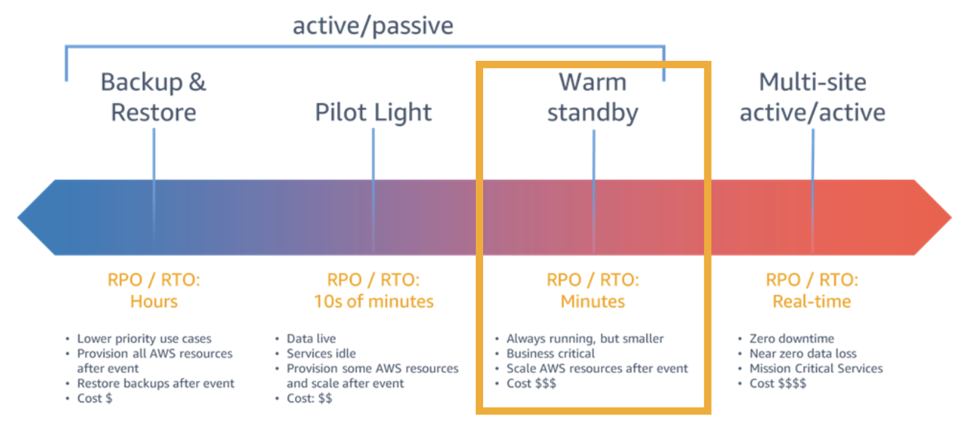
A comprehensive backup strategy is an essential part of an organization’s data protection plan to withstand, recover, and reduce any impact that might be sustained due to a security event. You should create an extensive backup strategy that defines which data must be backed up, how often data must be backed up, and monitoring of backup and recovery tasks. When you develop a comprehensive strategy for backing up and restoring data, you should first identify interruptions that may occur, and their potential business impact.

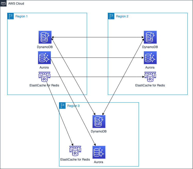
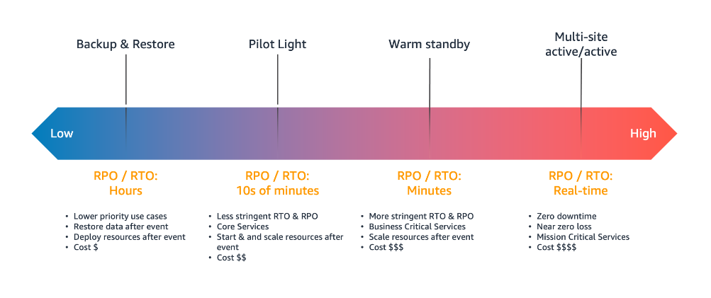
Your objective should be building a recovery strategy that brings your workload back up or avoids downtime within the acceptable Recovery Time Objective (RTO) and Recovery Point Objective (RPO). RTO is the acceptable delay between the interruption of service and restoration of service, and RPO is the acceptable amount of time since the last data recovery point. You should consider a granular backup strategy that includes all of the following: continuous backup cadence, Point-in-Time Recovery (PITR), file-level recovery, application data–level recovery, volume-level recovery, instance-level recovery, etc.

A well-designed backup strategy should include actions that can protect and recover your resources from ransomware, with detailed recovery requirements for your applications and their data dependencies. For example, while you establish preventive and detective controls to mitigate the risk of ransomware, you should also design the appropriate level of granularity for cross-region and/or cross-account copy and restore patterns, to ensure that administrators do not restore corrupt backup data in the event of a security event.

In some industries, when developing a backup strategy, you must also consider the regulations for data retention requirements. You should make sure your backup strategy is designed with the necessary retention requirements (per data classification level and/or resource type) sufficient to meet your regulatory needs.

Consult your security compliance teams to validate whether your backup resources and operations should be included or segmented from the scope of your compliance programs. In my experience as a PCI DSS Qualified Security Assessor (QSA), I’ve seen successful/more mature customers include backup and recovery as critical parts of their security program. This helps them understand where data is across their environment and appropriately define compliance scope.

Refer to Backup and Recovery Approaches Using AWS and the Reliability Pillar of the AWS Well-Architected Framework for architectural best practices for designing and operating reliable, secure, efficient, and cost-effective workloads in the cloud.

#2 – Incorporate backup in DR and BCP

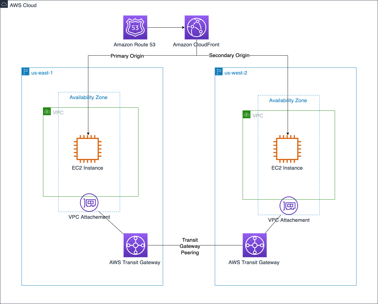
Disaster recovery (DR) is the process of preparing, responding, and recovering from a disaster. It is an important part of your resiliency strategy, and concerns how your workload responds when a disaster strikes. A disaster could be a technical failure, human action, or natural event. A Business Continuity Plan (BCP) outlines how an organization intends to continue normal business operations during an unplanned disruption.

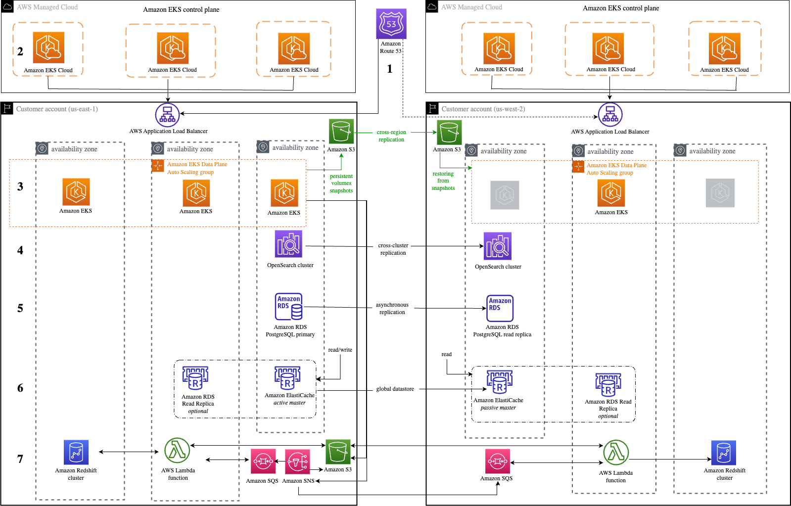
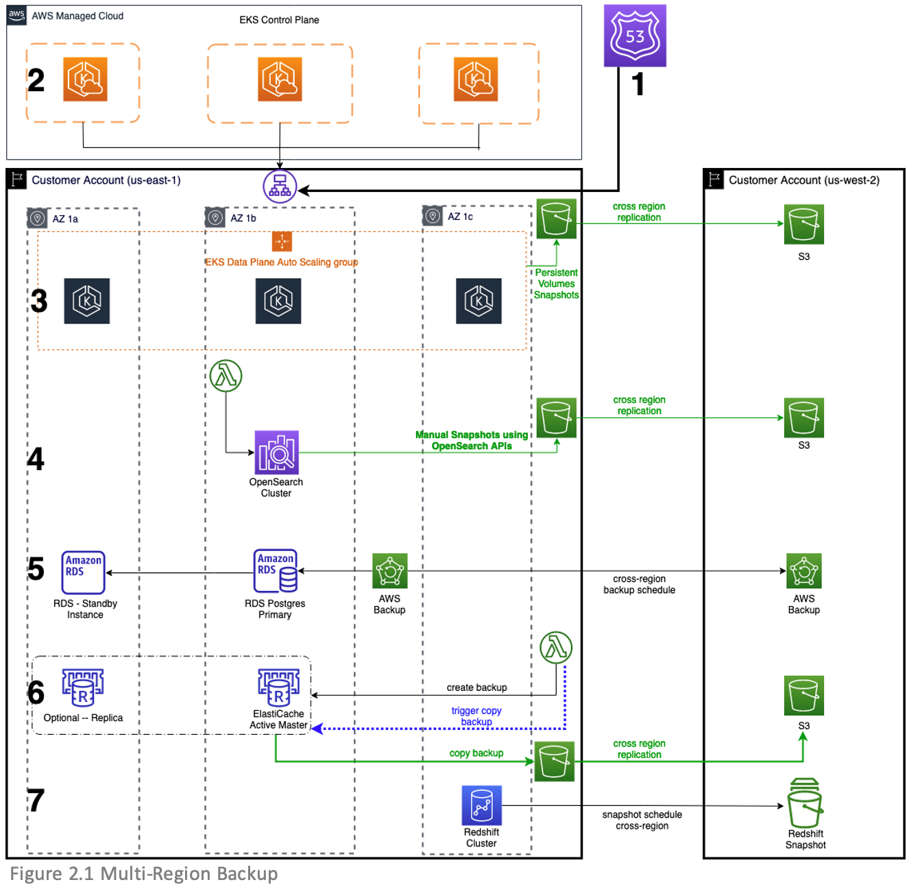
Your disaster recovery plan should be a subset of your organization’s business continuity plan (BCP) and you should incorporate AWS Backup procedures in your enterprise business continuity plan. For example, a security event that affects production data might require you to invoke a disaster recovery plan that fails over to backup data from another AWS Region. You should ensure that your employees are familiar with and have practiced using AWS Backup along with your organizational procedures, so that if disaster strikes, your organization can continue its normal operations with little or no service disruption.

#3 – Automate backup operations

Organizations should configure their backup plans and resource assignments to reflect their enterprise data protection policies. Automating and deploying backup policies or organization-wide backup plans allows you to standardize and scale your backup strategy. You can leverage AWS Organizations to centrally automate backup policies to implement, configure, manage, and govern backup activity across supported AWS resources by scheduling backup operations.

You should consider implementing infrastructure as code (IaC) and event-driven architecture as essential parts of your digital transformation and backup strategy, to improve productivity and govern infrastructure operations across multi-account environments. Automating backups allows you to reduce manual overhead from time-consuming configuration of your backups, minimizes the risk for errors, provides visibility on drift detection, and enhances backup policy compliance across multiple AWS workloads or accounts.

Implementing backup policies as code can help you meet data protection regulations, by configuring different requirements for your resource types, scaling your enterprise data protection strategy, and implementing lifecycle rules to specify how long before a recovery point either transitions to cold storage or is deleted, which can help optimize your costs.

When automating your backup operations, you can scale resource assignment options using AWS Tags and Resource IDs to automatically identify the AWS resources that store data for your business-critical applications and protect your data using immutable backups. This can help you prioritize security controls, such as access permissions and backup plans or policies.

#4 – Implement access control mechanisms

When thinking about security in the cloud, your foundational strategy should begin with a strong identity foundation to ensure a user has the right permissions to access data. Appropriate authentication and authorization can mitigate the risk of security events. The shared responsibility model requires AWS customers to implement access control policies. You can use AWS Identity and Access Management (IAM) service to create and manage access policies at scale.

When configuring access rights and permissions, you should implement the principle of least privilege by ensuring each user or system accessing your backup data or Vault is only given the permissions necessary to fulfill their job duties. Using AWS Backup, you should implement access control policies by setting access policies on backup vaults to protect your cloud workloads.

For example, implementing access control policies allows you to grant users access to create backup plans and on-demand backups, but still limit their ability to delete recovery points once they’ve been created. Using vault access policies, you can share a destination backup vault with a source AWS Account, user, or IAM role, as required by your business needs. Access policy can also allow you to share a backup vault with one or multiple accounts, or with your entire organization in AWS Organizations.

As you scale your workloads or migrate into AWS, you may need to centrally manage permissions to your backup vaults and operations. You should use service control policies (SCPs) to implement centralized control over the maximum available permissions for all accounts in your organization. This offers defense in depth, and ensures your users stay within the defined access control guidelines. To learn more, read how you can secure your AWS Backup data and operations using service control policies (SCPs).

To mitigate security risks such as unintended access to your backup resources and data, use AWS IAM Access Analyzer to identify any AWS Backup IAM role shared with an external entity such as AWS account, a root user, an IAM user or role, a federated user, an AWS service, an anonymous user, or other entity that you can use to create a filter.

#5 – Encrypt backup data and vault

Organizations increasingly need to improve their data security strategy, and may be required to meet data protection regulations as they scale in the cloud. The correct implementation of encryption methods can provide an additional layer of protection above foundational access control mechanisms providing a mitigation if your primary access control policies fail.

For example, if you configure overly permissive access control policies on your Backup data, your key management system or process can mitigate the maximum impact of a security event, since there are separate authorization mechanisms to access your data and encryption key which means that the backup data is only viewable as cipher text.

To get the most from AWS cloud encryption, you should encrypt data both in transit and at rest. To protect data in transit, AWS uses published API calls to access AWS Backup through the network using Transport Layer Security (TLS) protocol to provide encryption between you, your application and the Backup service. To protect data at rest, AWS offers cloud-native options of using AWS Key Managed System (KMS) or AWS CloudHSM which leverages Advanced Encryption Standard (AES) with 256-bit keys (AES-256), a strong industry-adopted algorithm for encrypting data. You should evaluate your data governance and regulatory requirements, and select the appropriate encryption service to encrypt your cloud data and backup vaults.

Encryption configuration differs depending on the resource type and backup operations across accounts or Regions. Certain resource types support the ability to encrypt your backups using a separate encryption key from the key used to encrypt the source resource. Since you are responsible for managing access controls to determine who can access your Backup data or vault encryption keys and under which conditions, you should use the policy language offered by AWS KMS to define access controls on keys. You can also use AWS Backup Audit Manager to confirm that your backup is properly encrypted.

To learn more, refer to the documentation on encryption for backups and backup copies.

AWS KMS multi-Region keys allows you to replicate keys from one Region into another. Multi-Region keys are designed to simplify encryption management when your encrypted data has to be copied into other Regions for disaster recovery. You should evaluate the need to implement multi-region KMS keys as part of your overall backup strategy.

#6 – Safeguard backups using immutable storage

Immutable storage allows organizations to write data in a Write Once Read Many (WORM) state. While in a WORM state, data can be written one time, read and used as often as needed after it has been committed or written to the storage medium. Immutable storage ensures data integrity is maintained and provides protection against deletes, overwrites, inadvertent and unauthorized access, ransomware compromise etc. Immutable storage offers an efficient mechanism to address potential security events with real impacts on your business operations.

Immutable storage can be used for better governance when paired with strong SCP restrictions, or can be used in a compliance WORM mode when the letter of the law (such as a legal hold) requires access to immutable data.

You can maintain data availability and integrity with AWS Backup Vault Lock to protect your backups* such that unauthorized entities cannot erase, alter or corrupt your customer or business data during the required retention period. AWS Backup Vault Lock helps you meet your organization’s data protection policies by preventing deletions by privileged users (including the AWS account root user), changes to your backup lifecycle settings, and updates that alter your defined retention period.

AWS Backup Vault Lock ensures immutability and adds an additional layer of defense that protects backups (recovery points) in your Backup Vaults, especially in highly- regulated industries with stringent integrity needs for backups and archives. AWS Backup Vault Lock makes sure your data is preserved along with a backup to recover from in case of unintended or malicious actions.

*The feature has not yet been assessed for compliance with the Securities and Exchange Commission (SEC) rule 17a-4(f) and the Commodity Futures Trading Commission (CFTC) in regulation 17 C.F.R. 1.31(b)-(c).

#7 – Implement backup monitoring and alerting

Backup jobs can fail. A failed job, such as backup, restore, or copy task, may have impact on subsequent steps in a process. When the initial backup job fails, there’s a high probability that other succeeding tasks will also fail. In such a scenario, you can best understand the course of events through monitoring and notification.

Enabling and configuring notifications to generate emails to monitor AWS Backup jobs gives you awareness of your backup activities, ensures you meet critical service-level agreements (SLAs), enhances your business-as-usual monitoring, and helps you meet compliance obligations. You can implement backup monitoring for your workloads by integrating AWS Backup with other AWS services and ticketing systems to perform automated investigation and escalation flows.

For example, use Amazon CloudWatch to track metrics, create alarms, and view dashboards, Amazon EventBridge to monitor AWS Backup processes and events, AWS CloudTrail to monitor AWS Backup API calls with detailed information on the time, source IP, users, and accounts making those calls, and Amazon Simple Notification Service (Amazon SNS) to subscribe to AWS Backup-related topics such as backup, restore, and copy events. Monitoring and alerting can provide organizational awareness for your backup jobs, which helps you respond to backup failures.

You can use AWS Backup Audit Manager to automatically generate evidence of your daily backup audit reports per account and Region. You can also scale your backup monitoring across multiple accounts by using a set of automation templates and dashboards (known as the backup observer solution) to obtain aggregated daily cross-account multi-Region AWS Backup reporting.

#8 – Audit backup configuration

Organizations should audit the compliance of AWS Backup policies against defined controls such as defined backup frequency. You should continuously and automatically track your backup activity and generate automatic reports to find and investigate backup operations or resources which are not compliant with your business requirements.

AWS Backup Audit Manager provides built-in, customizable, compliance controls that align with your business compliance and regulatory requirements. AWS Backup Audit Manager provides five backup governance control templates, including backup resources protected by backup plans, backup plan with a minimum frequency and minimum retention, etc. If you leverage infrastructure-as-code automation, you can use AWS Backup Audit Manager with AWS CloudFormation.

AWS Security Hub provides you with a comprehensive view of your security state in AWS and helps you check your environment against security best practices and industry standards such as AWS Foundational Security Best Practices controls. If you leverage AWS Security Hub within your cloud environment, we recommend you enable the AWS Foundational Security Best Practices, as it includes detective controls that can help with securing backups in AWS. The detective controls in AWS Backup Audit Manager and Security Hub are also mostly available as AWS managed rules in AWS Config.

#9 – Test data recovery capabilities

Ideally, any data stored as a backup must be able to be successfully restored when required. Your backup strategy must include testing your backups. A backup strategy is not effective if backed up data cannot be restored. You should regularly test your ability to find certain recovery points and restore them. While AWS Backup automatically copies tags from the resources it protects to the recovery points, tags are not copied from recovery points to the corresponding restored resources. To scale your inventory management and locate recovery points, you should consider retaining your tags on resources created by AWS Backup restore jobs, using AWS Backup events to trigger a tag replication process.

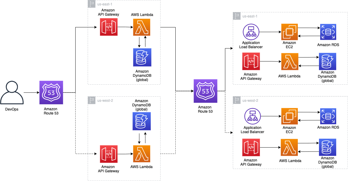
You can start your data recovery workflow by establishing data recovery patterns and then regularly test them. You should create a simple and repeatable process that allows you to perform continuous data recovery testing to increase confidence in your ability to recover backup data. For example, you can create a pattern to test a cross-account, cross-region restore operation from a central DR backup vault encrypted with a customer-managed KMS key to a source account backup vault encrypted with a different customer-managed KMS key.

If you don’t frequently test such restore operations, you may find that your assumptions on KMS encryption for cross-account, cross-region operations are incorrect. Oftentimes, the only backup recovery pattern that actually works is the path you test frequently. Through routine testing of supported backup resource types, you can spot early warnings that could potentially cause future disturbances and loss of critical data. If possible, maintain a limited but feasible number of recovery paths and patterns to prevent wasted storage space, optimize costs, and save time. It’s easier to fix the problem when a recovery test fails than losing valuable or critical data.

#10 – Incorporate backup in incident response plan

Security Incident Response Simulations (SIRS) are internal events that provide a structured opportunity to practice your incident response plan and procedures during a realistic scenario. It’s valuable to test your backup data and operations in creative SIRS activities to test yourself against the unexpected. This helps you validate your organizational readiness and develop comfort with the rare and unexpected. Your simulations must be realistic, and should involve cross-functional organizational teams required to respond to events.

Start with basic and easy simulation exercises, and work towards a full, complex event. For example, you can build a realistic model that consists of an Amazon Virtual Private Cloud and associated resources that simulate inadvertent overexposure of information or a potential data breach due to changes to policies and access control lists. Document lessons learned to evaluate how well your incident response plan worked, and to identify improvements that need to be made to future response procedures.

You can use AWS Backup to set up automated instance-level backups as AMIs and volume-level backups as snapshots across multiple AWS accounts. This can help your incident response team enhance their forensic process such as automated forensic disk collection, by providing a restore point that could reduce the scope and impact of potential security events such as ransomware.

Conclusion

In this blog post, I showed you the top ten security best practices and controls to protect your backup data in AWS. I encourage you to use these best practices to design and implement a backup and recovery strategy and architecture with multiple layers of controls that scales and achieves your business needs. To learn more about AWS Backup, refer to the AWS Backup documentation.

If you have feedback about this post, submit comments in the Comments section below. If you have questions about this post, start a new thread on the AWS Backup forum or contact AWS Support.

Further reading

Additional resources to consider:

Prescriptive Guidance: Backup and recovery approaches on AWS

Blog: Automate centralized backup at scale across AWS services using AWS Backup

Blog: Disaster Recovery (DR) Architecture on AWS, Part I: Strategies for Recovery in the Cloud

Blog: The importance of encryption and how AWS can help

Blog: Enhance the security posture of your backups with AWS Backup Vault Lock

Blog: Monitor, Evaluate, and Demonstrate Backup Compliance with AWS Backup Audit Manager

Blog: Create and share encrypted backups across accounts and Regions using AWS Backup

Blog: Simplify auditing your data protection policies with AWS Backup Audit Manager

Blog: Managing access to backups using service control policies with AWS Backup

Blog: Obtain aggregated daily cross-account multi-Region AWS Backup reporting

Want more AWS Security news? Follow us on Twitter.

Author

Ibukun Oyewumi

Ibukun is a Security Assurance Consultant at AWS. He focuses on helping customers architect, build, scale, and optimize security controls, risk management, and compliance.

Creating a Multi-Region Application with AWS Services – Part 2, Data and Replication

Post Syndicated from Joe Chapman original https://aws.amazon.com/blogs/architecture/creating-a-multi-region-application-with-aws-services-part-2-data-and-replication/

In Part 1 of this blog series, we looked at how to use AWS compute, networking, and security services to create a foundation for a multi-Region application.

Data is at the center of many applications. In this post, Part 2, we will look at AWS data services that offer native features to help get your data where it needs to be.

In Part 3, we’ll look at AWS application management and monitoring services to help you build, monitor, and maintain a multi-Region application.

Considerations with replicating data

Data replication across the AWS network can happen quickly, but we are still limited by the speed of light. For this reason, data consistency must be considered when building a multi-Region application. Generally speaking, the longer a physical distance is, the longer it will take the data to get there.

When building a distributed system, consider the consistency, availability, partition tolerance (CAP) theorem. This theorem states that an application can only pick 2 out of the 3, and tradeoffs should be considered.

  • Consistency – all clients always have the same view of data
  • Availability – all clients can always read and write data
  • Partition Tolerance – the system will continue to work despite physical partitions

CAP diagram

Achieving consistency and availability is common for single-Region applications. For example, when an application connects to a single in-Region database. However, this becomes more difficult with multi-Region applications due to the latency added by transferring data over long distances. For this reason, highly distributed systems will typically follow an eventual consistency approach, favoring availability and partition tolerance.

Replicating objects and files

To ensure objects are in multiple Regions, Amazon Simple Storage Service (Amazon S3) can be set up to replicate objects across AWS Regions automatically with one-way or two-way replication. A subset of objects in an S3 bucket can be replicated with S3 replication rules. If low replication lag is critical, S3 Replication Time Control can help meet requirements by replicating 99.99% of objects within 15 minutes, and most within seconds. To monitor the replication status of objects, Amazon S3 events and metrics will track replication and can send an alert if there’s an issue.

Traditionally, each S3 bucket has its own single, Regional endpoint. To simplify connecting to and managing multiple endpoints, S3 Multi-Region Access Points create a single global endpoint spanning multiple S3 buckets in different Regions. When applications connect to this endpoint, it will route over the AWS network using AWS Global Accelerator to the bucket with the lowest latency. Failover routing is also automatically handled if the connectivity or availability to a bucket changes.

For files stored outside of Amazon S3, AWS DataSync simplifies, automates, and accelerates moving file data across Regions and accounts. It supports homogeneous and heterogeneous file migrations across Elastic File System (Amazon EFS), Amazon FSx, AWS Snowcone, and Amazon S3. It can even be used to sync on-premises files stored on NFS, SMB, HDFS, and self-managed object storage to AWS for hybrid architectures.

File and object replication should be expected to be eventually consistent. The rate at which a given dataset can transfer is a function of the amount of data, I/O bandwidth, network bandwidth, and network conditions.

Copying backups

Scheduled backups can be set up with AWS Backup, which automates backups of your data to meet business requirements. Backup plans can automate copying backups to one or more AWS Regions or accounts. A growing number of services are supported, and this can be especially useful for services that don’t offer real-time replication to another Region such as Amazon Elastic Block Store (Amazon EBS) and Amazon Neptune.

Figure 1 shows how these data transfer services can be combined for each resource.

Storage replication services

Figure 1. Storage replication services

Spanning non-relational databases across Regions

Amazon DynamoDB global tables provide multi-Region and multi-writer features to help you build global applications at scale. A DynamoDB global table is the only AWS managed offering that allows for multiple active writers in a multi-Region topology (active-active and multi-Region). This allows for applications to read and write in the Region closest to them, with changes automatically replicated to other Regions.

Global reads and fast recovery for Amazon DocumentDB (with MongoDB compatibility) can be achieved with global clusters. These clusters have a primary Region that handles write operations. Dedicated storage-based replication infrastructure enables low-latency global reads with a lag of typically less than one second.

Keeping in-memory caches warm with the same data across Regions can be critical to maintain application performance. Amazon ElastiCache for Redis offers global datastore to create a fully managed, fast, reliable, and secure cross-Region replica for Redis caches and databases. With global datastore, writes occurring in one Region can be read from up to two other cross-Region replica clusters – eliminating the need to write to multiple caches to keep them warm.

Spanning relational databases across Regions

For applications that require a relational data model, Amazon Aurora global database provides for scaling of database reads across Regions in Aurora PostgreSQL-compatible and MySQL-compatible editions. Dedicated replication infrastructure utilizes physical replication to achieve consistently low replication lag that outperforms the built-in logical replication database engines offer, as shown in Figure 2.

SysBench OLTP (write-only) stepped every 600 seconds on R4.16xlarge

Figure 2. SysBench OLTP (write-only) stepped every 600 seconds on R4.16xlarge

With Aurora global database, one primary Region is designated as the writer, and secondary Regions are dedicated to reads. Aurora MySQL supports write forwarding, which forwards write requests from a secondary Region to the primary Region to simplify logic in application code. Failover testing can happen by utilizing managed planned failover, which will change the active write cluster to another Region while keeping the replication topology intact. All databases discussed in this post employ eventual consistency when used across Regions, but Aurora PostgreSQL has an option to set the maximum a replica lag allowed with managed recovery point objective (managed RPO).

Logical replication, which utilizes a database engine’s built-in replication technology, can be set up for Amazon Relational Database Service (Amazon RDS) for MariaDB, MySQL, Oracle, PostgreSQL, and Aurora databases. A cross-Region read replica will receive these changes from the writer in the primary Region. For applications built on RDS for Microsoft SQL Server, cross-Region replication can be achieved by utilizing the AWS Database Migration Service. Cross-Region replicas allow for quicker local reads and can reduce data loss and recovery times in the case of a disaster by being promoted to a standalone instance.

For situations where a longer RPO and recovery time objective (RTO) are acceptable, backups can be copied across Regions. This is true for all of the relational and non-relational databases mentioned in this post, except for ElastiCache for Redis. Amazon Redshift can also automatically do this for your data warehouse. Backup copy times will vary depending on size and change rates.

A purpose-built database strategy offers many benefits, Figure 3 forms a purpose-built global database architecture.

Purpose-built global database architecture

Figure 3. Purpose-built global database architecture

Summary

Data is at the center of almost every application. In this post, we reviewed AWS services that offer cross-Region data replication to get your data where it needs to be quickly. Whether you need faster local reads, an active-active database, or simply need your data durably stored in a second Region, we have a solution for you. In the 3rd and final post of this series, we’ll cover application management and monitoring features.

Ready to get started? We’ve chosen some AWS Solutions, AWS Blogs, and Well-Architected labs to help you!

Related posts

Creating a Multi-Region Application with AWS Services – Part 1, Compute and Security

Post Syndicated from Joe Chapman original https://aws.amazon.com/blogs/architecture/creating-a-multi-region-application-with-aws-services-part-1-compute-and-security/

Building a multi-Region application requires lots of preparation and work. Many AWS services have features to help you build and manage a multi-Region architecture, but identifying those capabilities across 200+ services can be overwhelming.

In this 3-part blog series, we’ll explore AWS services with features to assist you in building multi-Region applications. In Part 1, we’ll build a foundation with AWS security, networking, and compute services. In Part 2, we’ll add in data and replication strategies. Finally, in Part 3, we’ll look at the application and management layers.

Considerations before getting started

AWS Regions are built with multiple isolated and physically separate Availability Zones (AZs). This approach allows you to create highly available Well-Architected workloads that span AZs to achieve greater fault tolerance. There are three general reasons that you may need to expand beyond a single Region:

  • Expansion to a global audience as an application grows and its user base becomes more geographically dispersed, there can be a need to reduce latencies for different parts of the world.
  • Reducing Recovery Point Objectives (RPO) and Recovery Time Objectives (RTO) as part of disaster recovery (DR) plan.
  • Local laws and regulations may have strict data residency and privacy requirements that must be followed.

Ensuring security, identity, and compliance

Creating a security foundation starts with proper authentication, authorization, and accounting to implement the principle of least privilege. AWS Identity and Access Management (IAM) operates in a global context by default. With IAM, you specify who can access which AWS resources and under what conditions. For workloads that use directory services, the AWS Directory Service for Microsoft Active Directory Enterprise Edition can be set up to automatically replicate directory data across Regions. This allows applications to reduce lookup latencies by using the closest directory and creates durability by spanning multiple Regions.

Applications that need to securely store, rotate, and audit secrets, such as database passwords, should use AWS Secrets Manager. It encrypts secrets with AWS Key Management Service (AWS KMS) keys and can replicate secrets to secondary Regions to ensure applications are able to obtain a secret in the closest Region.

Encrypt everything all the time

AWS KMS can be used to encrypt data at rest, and is used extensively for encryption across AWS services. By default, keys are confined to a single Region. AWS KMS multi-Region keys can be created to replicate keys to a second Region, which eliminates the need to decrypt and re-encrypt data with a different key in each Region.

AWS CloudTrail logs user activity and API usage. Logs are created in each Region, but they can be centralized from multiple Regions and multiple accounts into a single Amazon Simple Storage Service (Amazon S3) bucket. As a best practice, these logs should be aggregated to an account that is only accessible to required security personnel to prevent misuse.

As your application expands to new Regions, AWS Security Hub can aggregate and link findings to a single Region to create a centralized view across accounts and Regions. These findings are continuously synced between Regions to keep you updated on global findings.

We put these features together in Figure 1.

Multi-Region security, identity, and compliance services

Figure 1. Multi-Region security, identity, and compliance services

Building a global network

For resources launched into virtual networks in different Regions, Amazon Virtual Private Cloud (Amazon VPC) allows private routing between Regions and accounts with VPC peering. These resources can communicate using private IP addresses and do not require an internet gateway, VPN, or separate network appliances. This works well for smaller networks that only require a few peering connections. However, as the number of peered connections increases, the mesh of peered connections can become difficult to manage and troubleshoot.

AWS Transit Gateway can help reduce these difficulties by creating a central transitive hub to act as a cloud router. A Transit Gateway’s routing capabilities can expand to additional Regions with Transit Gateway inter-Region peering to create a globally distributed private network.

Building a reliable, cost-effective way to route users to distributed Internet applications requires highly available and scalable Domain Name System (DNS) records. Amazon Route 53 does exactly that.

Route 53 routing policies can route traffic to a record with the lowest latency, or automatically fail over a record. If a larger failure occurs, the Route 53 Application Recovery Controller can simplify the monitoring and failover process for application failures across Regions, AZs, and on-premises.

Amazon CloudFront’s content delivery network is truly global, built across 300+ points of presence (PoP) spread throughout the world. Applications that have multiple possible origins, such as across Regions, can use CloudFront origin failover to automatically fail over the origin. CloudFront’s capabilities expand beyond serving content, with the ability to run compute at the edge. CloudFront functions make it easy to run lightweight JavaScript functions, and AWS Lambda@Edge makes it easy to run Node.js and Python functions across these 300+ PoPs.

AWS Global Accelerator uses the AWS global network infrastructure to provide two static anycast IPs for your application. It automatically routes traffic to the closest Region deployment, and if a failure is detected it will automatically redirect traffic to a healthy endpoint within seconds.

Figure 2 brings these features together to create a global network across two Regions.

AWS VPC connectivity and content delivery

Figure 2. AWS VPC connectivity and content delivery

Building the compute layer

An Amazon Elastic Compute Cloud (Amazon EC2) instance is based on an Amazon Machine Image (AMI). An AMI specifies instance configurations such as the instance’s storage, launch permissions, and device mappings. When a new standard image needs to be created, EC2 Image Builder can be used to streamline copying AMIs to selected Regions.

Although EC2 instances and their associated Amazon Elastic Block Store (Amazon EBS) volumes live in a single AZ, Amazon Data Lifecycle Manager can automate the process of taking and copying EBS snapshots across Regions. This can enhance DR strategies by providing a relatively easy cold backup-and-restore option for EBS volumes.

As an architecture expands into multiple Regions, it can become difficult to track where instances are provisioned. Amazon EC2 Global View helps solve this by providing a centralized dashboard to see Amazon EC2 resources such as instances, VPCs, subnets, security groups, and volumes in all active Regions.

Microservice-based applications that use containers benefit from quicker start-up times. Amazon Elastic Container Registry (Amazon ECR) can help ensure this happens consistently across Regions with private image replication at the registry level. An ECR private registry can be configured for either cross-Region or cross-account replication to ensure your images are ready in secondary Regions when needed.

We bring these compute layer features together in Figure 3.

AMI and EBS snapshot copy across Regions

Figure 3. AMI and EBS snapshot copy across Regions

Summary

It’s important to create a solid foundation when architecting a multi-Region application. These foundations pave the way for you to move fast in a secure, reliable, and elastic way as you build out your application. In this post, we covered options across AWS security, networking, and compute services that have built-in functionality to take away some of the undifferentiated heavy lifting. We’ll cover data, application, and management services in future posts.

Ready to get started? We’ve chosen some AWS Solutions and AWS Blogs to help you!

Looking for more architecture content? AWS Architecture Center provides reference architecture diagrams, vetted architecture solutions, Well-Architected best practices, patterns, icons, and more!

Disaster Recovery with AWS Managed Services, Part I: Single Region

Post Syndicated from Dhruv Bakshi original https://aws.amazon.com/blogs/architecture/disaster-recovery-with-aws-managed-services-part-i-single-region/

This 3-part blog series discusses disaster recovery (DR) strategies that you can implement to ensure your data is safe and that your workload stays available during a disaster. In Part I, we’ll discuss the single AWS Region/multi-Availability Zone (AZ) DR strategy.

The strategy outlined in this blog post addresses how to integrate AWS managed services into a single-Region DR strategy. This will minimize maintenance and operational overhead, create fault-tolerant systems, ensure high availability, and protect your data with robust backup/recovery processes. This strategy replicates workloads across multiple AZs and continuously backs up your data to another Region with point-in-time recovery, so your application is safe even if all AZs within your source Region fail.

Implementing the single Region/multi-AZ strategy

The following sections list the components of the example application presented in Figure 1, which illustrates a multi-AZ environment with a secondary Region that is strictly utilized for backups. This example architecture refers to an application that processes payment transactions that has been modernized with AMS. We’ll show you which AWS services it uses and how they work to maintain the single Region/multi-AZ strategy.

Single Region/multi-AZ with secondary Region for backups

Figure 1. Single Region/multi-AZ with secondary Region for backups

Amazon EKS control plane

Amazon Elastic Kubernetes Service (Amazon EKS) runs the Kubernetes management infrastructure across multiple AZs to eliminate a single point of failure.

This means that if your infrastructure or AZ fails, it will automatically scale control plane nodes based on load, automatically detect and replace unhealthy control plane instances, and restart them across the AZs within the Region as needed.

Amazon EKS data plane

Instead of creating individual Amazon Elastic Compute Cloud (Amazon EC2) instances, create worker nodes using an Amazon EC2 Auto Scaling group. Join the group to a cluster, and the group will automatically replace any terminated or failed nodes if an AZ fails. This ensures that the cluster can always run your workload.

Amazon ElastiCache

Amazon ElastiCache continually monitors the state of the primary node. If the primary node fails, it will promote the read replica with the least replication lag to primary. A replacement read replica is then created and provisioned in the same AZ as the failed primary. This is to ensure high availability of the service and application.

An ElastiCache for Redis (cluster mode disabled) cluster with multiple nodes has three types of endpoints: the primary endpoint, the reader endpoint and the node endpoints. The primary endpoint is a DNS name that always resolves to the primary node in the cluster.

Amazon Redshift

Currently, Amazon Redshift only supports single-AZ deployments. Although there are ways to work around this, we are focusing on cluster relocation. Parts II and III of this series will show you how to implement this service in a multi-Region DR deployment.

Cluster relocation enables Amazon Redshift to move a cluster to another AZ with no loss of data or changes to your applications. When Amazon Redshift relocates a cluster to a new AZ, the new cluster has the same endpoint as the original cluster. Your applications can reconnect to the endpoint and continue operations without modifications or loss of data.

Note: Amazon Redshift may also relocate clusters in non-AZ failure situations, such as when issues in the current AZ prevent optimal cluster operation or to improve service availability.

Amazon OpenSearch Service

Deploying your data nodes into three AZs with Amazon OpenSearch Service (formerly Amazon Elasticsearch Service) can improve the availability of your domain and increase your workload’s tolerance for AZ failures.

Amazon OpenSearch Service automatically deploys into three AZs when you select a multi-AZ deployment. This distribution helps prevent cluster downtime if an AZ experiences a service disruption. When you deploy across three AZs, Amazon OpenSearch Service distributes master nodes equally across all three AZs. That way, in the rare event of an AZ disruption, two master nodes will still be available.

Amazon OpenSearch Service also distributes primary shards and their corresponding replica shards to different zones. In addition to distributing shards by AZ, Amazon OpenSearch Service distributes them by node. When you deploy the data nodes across three AZs with one replica enabled, shards are distributed across the three AZs.

Note: For more information on multi-AZ configurations, please refer to the AZ disruptions table.

Amazon RDS PostgreSQL

Amazon Relational Database Service (Amazon RDS) handles failovers automatically so you can resume database operations as quickly as possible.

In a Multi-AZ deployment, Amazon RDS automatically provisions and maintains a synchronous standby replica in a different AZ. The primary DB instance is synchronously replicated across AZs to a standby replica. If an AZ or infrastructure fails, Amazon RDS performs an automatic failover to the standby. This minimizes the disruption to your applications without administrative intervention.

Backing up data across Regions

Here is how the managed services back up data to a secondary Region:

  • Manage snapshots of persistent volumes for Amazon EKS with Velero. Amazon Simple Storage Service (Amazon S3) stores these snapshots in an S3 bucket in the primary Region. Amazon S3 replicates these snapshots to an S3 bucket in another Region via S3 cross-Region replication.
  • Create a manual snapshot of Amazon OpenSearch Service clusters, which are stored in a registered repository like Amazon S3. You can do this manually or automate it via an AWS Lambda function, which automatically and asynchronously copy objects across Regions.
  • Use manual backups and copy API calls for Amazon ElastiCache to establish a snapshot and restore strategy in a secondary Region. You can manually back your data up to an S3 bucket or automate the backup via Lambda. Once your data is backed up, a snapshot of the ElastiCache cluster will be stored in an S3 bucket. Then S3 cross-Region replication will asynchronously copy the backup to an S3 bucket in a secondary Region.
  • Take automatic, incremental snapshots of your data periodically with Amazon Redshift and save them to Amazon S3. You can precisely control when snapshots are taken and can create a snapshot schedule and attach it to one or more clusters. You can also configure a cross-Region snapshot copy, which automatically copies your automated and manual snapshots to another Region.
  • Use AWS Backup to support AWS resources and third-party applications. AWS Backup copies RDS backups to multiple Regions on demand or automatically as part of a scheduled backup plan.

Note: You can add a layer of protection to your backups through AWS Backup Vault Lock and S3 Object Lock.

Conclusion

The single Region/multi-AZ strategy safeguards your workloads against a disaster that disrupts an Amazon data center by replicating workloads across multiple AZs in the same Region. This blog shows you how AWS managed services automatically fails over between AZs without interruption when experiencing a localized disaster, and how backups to a separate Region ensure data protection.

In the next post, we will discuss a multi-Region warm standby strategy for the same application stack illustrated in this post.

Related information

Disaster Recovery (DR) for a Third-party Interactive Voice Response on AWS

Post Syndicated from Priyanka Kulkarni original https://aws.amazon.com/blogs/architecture/disaster-recovery-dr-for-a-third-party-interactive-voice-response-on-aws/

Voice calling systems are prevalent and necessary to many businesses today. They are usually designed to provide a 24×7 helpline support across multiple domains and use cases. Reliability and availability of such systems are important for a good customer experience. The thoughtful design of a cost-optimized solution will allow your business to sustain the system into the future.

We address a scenario in which you are mandated to host the workload on a corporate data center (DC), and configure the backup site on Amazon Web Services (AWS). Since the primary objective of a backup site is disaster recovery (DR) management, this site is often referred to as a DR site.

Disaster Recovery on AWS

DR strategy defines the recovery objectives for downtime and data loss. The workload has a recovery time objective (RTO) and a recovery point objective (RPO). RTO is the maximum acceptable delay between the interruption of service and the restoration of service. RPO is the maximum acceptable amount of time since the last data recovery point. AWS defines four DR strategies in increasing order of complexity, and decreasing order of RTO and RPO. These are backup and restore, active/passive (pilot light or warm standby), or active/active.

Figure 1. Disaster recovery (DR) options

Figure 1. Disaster recovery (DR) options

In our use case, the DR site on AWS must serve the user traffic with RPO and RTO in seconds. Warm standby is the optimal choice in this case. It is a scaled-down version of a fully functional environment, and is always running in the cloud.

Amazon Connect is an omnichannel cloud contact center that helps you provide great customer service at a lower cost. But in some situations, Amazon Connect may not be available. In other cases, the customer may want to use their home developed or third-party contact center application. Our solution is designed to help in both these scenarios.

This architecture enables customers facing challenges of cost overhead with redundant Session Initiation Protocol (SIP) trunks for the DC and DR sites. It allows you to optimize your spend and yet retain a reliable workflow.

SIP trunk communication on AWS

Let’s see how the SIP trunk termination on the AWS network handles the failover scenario of a third-party IVR application installed on Amazon EC2 at the DR site.

There will be two connections made from the AWS Direct Connect location (DX). The first will be for a point-to-point connectivity between the corporate DC and the AWS DR site. The second connection will be originating from the multiplexer (MUX) of the telecom provider who is providing you the SIP trunk.

The telecom provider will lay the SIP trunk from its MUX to the customer router at the DX location. At this point, the mode of communication becomes IP-based. The telecom provider will send the call to the IP address attached to the Network Load Balancer (NLB) in Amazon Virtual Private Cloud (VPC).

Figure 2. Communication circuitry at telecom side

Figure 2. Communication circuitry at telecom side

AWS Network Load Balancers can now distribute traffic to AWS resources using their IP addresses and instance IDs as targets. You can also distribute the traffic with on-premises resources over AWS Direct Connect. Load balancing across AWS and on-premises resources using the same load balancer streamlines migrate-to-cloud, burst-to-cloud, or failover-to-cloud.

In the backup site, the NLB will point to the Session Border Controller (SBC). This is a special-purpose device that protects and regulates IP communications flows. You can bring your own SBC, or you can use an SBC offered in the AWS Marketplace.

Best practices for high availability of IVR solution on AWS

  • Configure the multiple Availability Zone (Multi-AZ) SBC setup
  • Make sure that the telecom provider for the SIP trunk is different from the internet service provider (ISP). This is for last mile connectivity for the DC from Direct Connect
  • Consider redundancy for Direct Connect by using a Site-to-Site VPN tunnel
Figure 3. Solution architecture of DR on AWS for a third-party IVR solution

Figure 3. Solution architecture of DR on AWS for a third-party IVR solution

Communication flow for an IVR solution deployed on a corporate DC and its DR on AWS

  1. The callers are received on the telecom providers SIP line, which terminates on the AWS Direct Connect location.
  2. At the DX location, you will configure a route in the AWS router to send the traffic to the IP address of the NLB. The NLB should be configured to perform health checks on the virtual machine in your on-premises DC. Based on these health checks, the NLB will do the routing and the failover.
  3. In a live scenario with successful health checks at the DC, the NLB will forward the call to the IP of the on-premises virtual machine. This is where the IVR application will be installed.
  4. The communication between the NLB in Amazon VPC and the virtual machine in DC, will happen over Direct Connect.
  5. In a DR scenario, the NLB will failover the communication to SBCs in Amazon VPC.

Conclusion

This solution is useful when a third-party IVR system is deployed in a corporate data center, and the passive DR site is hosted on AWS. Cost optimization on telecom components is an important aspect of this design. AWS Direct Connect provides dedicated connectivity to the AWS environment, from 50 Mbps up to 10 Gbps. This gives you managed and controlled latency. It also provides provisioned bandwidth, so your workload can connect to AWS resources in a reliable, scalable, and cost-effective way.

The solution in this blog explains the end-to-end flow of communication, from the user to the IVR agents. It also provides insights into managing failover and failback between DR and the DR site.

Further Reading:

Disaster recovery compliance in the cloud, part 2: A structured approach

Post Syndicated from Dan MacKay original https://aws.amazon.com/blogs/security/disaster-recovery-compliance-in-the-cloud-part-2-a-structured-approach/

Compliance in the cloud is fraught with myths and misconceptions. This is particularly true when it comes to something as broad as disaster recovery (DR) compliance where the requirements are rarely prescriptive and often based on legacy risk-mitigation techniques that don’t account for the exceptional resilience of modern cloud-based architectures. For regulated entities subject to principles-based supervision such as many financial institutions (FIs), the responsibility lies with the FI to determine what’s necessary to adequately recover from a disaster event. Without clear instructions, FIs are susceptible to making incorrect assumptions regarding their compliance requirements for DR.

In Part 1 of this two-part series, I provided some examples of common misconceptions FIs have about compliance requirements for disaster recovery in the cloud. In Part 2, I outline five steps you can take to avoid these misconceptions when architecting DR-compliant workloads for deployment on Amazon Web Services (AWS).

1. Identify workloads planned for deployment

It’s common for FIs to have a portfolio of workloads they are considering deploying to the cloud and often want to know that they can be compliant across the board. But compliance isn’t a one-size-fits-all domain—it’s based on the characteristics of each workload. For example, does the workload contain personally identifiable information (PII)? Will it be used to store, process, or transmit credit card information? Compliance is dependent on the answers to questions such as these and must be assessed on a case-by-case basis. Therefore, the first step in architecting for compliance is to identify the specific workloads you plan to deploy to the cloud. This way, you can assess the requirements of these specific workloads and not be distracted by aspects of compliance that might not be relevant.

2. Define the workload’s resiliency requirements

Resiliency is the ability of a workload to recover from infrastructure or service disruptions. DR is an important part of your resiliency strategy and concerns how your workload responds to a disaster event. DR strategies on AWS range from simple, low cost options such as backup and restore, to more complex options such as multi-site active-active, as shown in Figure 1.
 

For more information, I encourage you to read Seth Eliot’s blog series on DR Architecture on AWS as well as the AWS whitepaper Disaster Recovery of Workloads on AWS: Recovery in the Cloud.

The DR strategy you choose for a particular workload is dependent on your organization’s requirements for avoiding loss of data—known as the recovery point objective (RPO)—and reducing downtime where the workload isn’t available —known as the recovery time objective (RTO). RPO and RTO are key factors for determining the minimum architectural specifications necessary to meet the workload’s resiliency requirements. For example, can the workload’s RPO and RTO be achieved using a multi-AZ architecture in a single AWS Region, or do the resiliency requirements necessitate deploying the workload across multiple AWS Regions? Even if your workload is not subject to explicit compliance requirements for resiliency, understanding these requirements is necessary for assessing other aspects of DR compliance, including data residency and geodiversity.

3. Confirm the workload’s data residency requirements

As I mentioned in Part 1, data residency requirements might restrict which AWS Region or Regions you can deploy your workload to. Therefore, you need to confirm whether the workload is subject to any data residency requirements within applicable laws and regulations, corporate policies, or contractual obligations.

In order to properly assess these requirements, you must review the explicit language of the requirements so as to understand the specific constraints they impose. You should also consult legal, privacy, and compliance subject-matter specialists to help you interpret these requirements based on the characteristics of the workload. For example, do the requirements specifically state that the data cannot leave the country, or can the requirement be met so long as the data can be accessed from that country? Does the requirement restrict you from storing a copy of the data in another country—for example, for backup and recovery purposes? What if the data is encrypted and can only be read using decryption keys kept within the home country? Consulting subject-matter specialists to help interpret these requirements can help you avoid making overly restrictive assumptions and imposing unnecessary constraints on the workload’s architecture.

4. Confirm the workload’s geodiversity requirements

A single Region, multiple-AZ architecture is often sufficient to meet a workload’s resiliency requirements. However, if the workload is subject to geodiversity requirements, the distance between the AZs in an AWS Region might not conform to the minimum distance between individual data centers specified by the requirements. Therefore, it’s critical to confirm whether any geodiversity requirements apply to the workload.

Like data residency, it’s important to assess the explicit language of geodiversity requirements. Are they written down in a regulation or corporate policy, or are they just a recommended practice? Can the requirements be met if the workload is deployed across three or more AZs even if the minimum distance between those AZs is less than the specified minimum distance between the primary and backup data centers? If it’s a corporate policy, does it allow for exceptions if an alternative method provides equal or greater resiliency than asynchronous replication between two geographically distant data centers? Or perhaps the corporate policy is outdated and should be revised to reflect modern risk mitigation techniques. Understanding these parameters can help you avoid unnecessary constraints as you assess architectural options for your workloads.

5. Assess architectural options to meet the workload’s requirements

Now that you understand the workload’s requirements for resiliency, data residency, and geodiversity, you can assess the architectural options that meet these requirements in the cloud.

As per AWS Well-Architected best practices, you should strive for the simplest architecture necessary to meet your requirements. This includes assessing whether the workload can be accommodated within a single AWS Region. If the workload is constrained by explicit geographic diversity requirements or has resiliency requirements that cannot be accommodated by a single AWS Region, then you might need to architect the workload for deployment across multiple AWS Regions. If the workload is also constrained by explicit data residency requirements, then it might not be possible to deploy to multiple AWS Regions. In cases such as these, you can work with our AWS Solution Architects to assess hybrid options that might meet your compliance requirements, such as using AWS Outposts, Amazon Elastic Container Service (Amazon ECS) Anywhere, or Amazon Elastic Kubernetes Service (Amazon EKS) Anywhere. Another option may be to consider a DR solution in which your on-premises infrastructure is used as a backup for a workload running on AWS. In some cases, this might be a long-term solution. In others, it might be an interim solution until certain constraints can be removed—for example, a change to corporate policy or the introduction of additional AWS Regions in a particular country.

Conclusion

Let’s recap by summarizing some guiding principles for architecting compliant DR workloads as outlined in this two-part series:

  • Avoid assumptions; confirm the facts. If it’s not written down, it’s unlikely to be considered a mandatory compliance requirement.
  • Consult the experts. Legal, privacy, and compliance, as well as AWS Solution Architects, AWS security and compliance specialists, and other subject-matter specialists.
  • Avoid generalities; focus on the specifics. There is no one-size-fits-all approach.
  • Strive for simplicity, not zero risk. Don’t use multiple AWS Regions when one will suffice.
  • Don’t get distracted by exceptions. Focus on your current requirements, not workloads you’re not yet prepared to deploy to the cloud.

If you have feedback about this post, submit comments in the Comments section below.

Want more AWS Security how-to content, news, and feature announcements? Follow us on Twitter.

Author

Dan MacKay

Dan is the Financial Services Compliance Specialist for AWS Canada. As a member of the Worldwide Financial Services Security & Compliance team, Dan advises financial services customers on best practices and practical solutions for cloud-related governance, risk, and compliance. He specializes in helping AWS customers navigate financial services and privacy regulations applicable to the use of cloud technology in Canada.

Disaster recovery compliance in the cloud, part 1: Common misconceptions

Post Syndicated from Dan MacKay original https://aws.amazon.com/blogs/security/disaster-recovery-compliance-in-the-cloud-part-1-common-misconceptions/

Compliance in the cloud can seem challenging, especially for organizations in heavily regulated sectors such as financial services. Regulated financial institutions (FIs) must comply with laws and regulations (often in multiple jurisdictions), global security standards, their own corporate policies, and even contractual obligations with their customers and counterparties. These various compliance requirements may impose constraints on how their workloads can be architected for the cloud, and may require interpretation on what FIs must do in order to be compliant. It’s common for FIs to make assumptions regarding their compliance requirements, which can result in unnecessary costs and increased complexity, and might not align with their strategic objectives. A modern, rationalized approach to compliance can help FIs avoid imposing unnecessary constraints while meeting their mandatory requirements.

In my role as an Amazon Web Services (AWS) Compliance Specialist, I work with our financial services customers to identify, assess, and determine solutions to address their compliance requirements as they move to the cloud. One of the most common challenges customers ask me about is how to comply with disaster recovery (DR) requirements for workloads they plan to run in the cloud. In this blog post, I share some of the typical misconceptions FIs have about DR compliance in the cloud. In Part 2, I outline a structured approach to designing compliant architectures for your DR workloads. As my primary market is Canada, the examples in this blog post largely pertain to FIs operating in Canada, but the principles and best practices are relevant to regulated organizations in any country.

“Why isn’t there a checklist for compliance in the cloud?”

Compliance requirements are sometimes prescriptive: “if X, then you must do Y.” When requirements are prescriptive, it’s usually clear what you must do in order to be compliant. For example, the Payment Card Industry Data Security Standard (PCI DSS) requirement 8.2.4 obliges companies that process, store, or transmit credit card information to “change user passwords/passphrases at least once every 90 days.” But in the financial services sector, compliance requirements for managing operational risks can be subjective. When regulators take what is known as a principles-based approach to setting regulatory expectations, each FI is required to assess their specific risks and determine the mitigating controls necessary to conform with the organization’s tolerance for operational risk. Because the rules aren’t prescriptive, there is no “checklist for achieving compliance.” Instead, principles-based requirements are guidelines that FIs are expected to consider as they design and implement technology solutions. They are, by definition, subject to interpretation and can be prone to myths and misconceptions among FIs and their service providers. To illustrate this, let’s look at two aspects of DR that are frequently misunderstood within the Canadian financial services industry: data residency and geodiversity.

“My data has to stay in country X”

Data residency or data localization is a requirement for specific data-sets processed and stored in an IT system to remain within a specific jurisdiction (for example, a country). As discussed in our Policy Perspectives whitepaper, contrary to historical perspectives, data residency doesn’t provide better security. Most cyber-attacks are perpetrated remotely and attackers aren’t deterred by the physical location of their victims. In fact, data residency can run counter to an organization’s objectives for security and resilience. For example, data residency requirements can limit the options our customers have when choosing the AWS Region or Regions in which to run their production workloads. This is especially challenging for customers who want to use multiple Regions for backup and recovery purposes.

It’s common for FIs operating in Canada to assume that they’re required to keep their data—particularly customer data—in Canada. In reality, there’s very little from a statutory perspective that imposes such a constraint. None of the private sector privacy laws include data residency requirements, nor do any of the financial services regulatory guidelines. There are some place of records requirements in Canadian federal financial services legislation such as The Bank Act and The Insurance Companies Act, but these are relatively narrow in scope and apply primarily to corporate records. For most Canadian FIs, their requirements are more often a result of their own corporate policies or contractual obligations, not externally imposed by public policies or regulations.

“My data centers have to be X kilometers apart”

Geodiversity—short for geographic diversity—is the concept of maintaining a minimum distance between primary and backup data processing sites. Geodiversity is based on the principle that requiring a certain distance between data centers mitigates the risk of location-based disruptions such as natural disasters. The principle is still relevant in a cloud computing context, but is not the only consideration when it comes to planning for DR. The cloud allows FIs to define operational resilience requirements instead of limiting themselves to antiquated business continuity planning and DR concepts like physical data center implementation requirements. Legacy disaster recovery solutions and architectures, and lifting and shifting such DR strategies into the cloud, can diminish the potential benefits of using the cloud to improve operational resilience. Modernizing your information technology also means modernizing your organization’s approach to DR.

In the cloud, vast physical distance separation is an anti-pattern—it’s an arbitrary metric that does little to help organizations achieve availability and recovery objectives. At AWS, we design our global infrastructure so that there’s a meaningful distance between the Availability Zones (AZs) within an AWS Region to support high availability, but close enough to facilitate synchronous replication across those AZs (an AZ being a cluster of data centers). Figure 1 shows the relationship between Regions, AZs, and data centers.
 

Synchronous replication across multiple AZs enables you to minimize data loss (defined as the recovery point objective or RPO) and reduce the amount of time that workloads are unavailable (defined as the recovery time objective or RTO). However, the low latency required for synchronous replication becomes less achievable as the distance between data centers increases. Therefore, a geodiversity requirement that mandates a minimum distance between data centers that’s too far for synchronous replication might prohibit you from taking advantage of AWS’s multiple-AZ architecture. A multiple-AZ architecture can achieve RTOs and RPOs that aren’t possible with a simple geodiversity mitigation strategy. For more information, refer to the AWS whitepaper Disaster Recovery of Workloads on AWS: Recovery in the Cloud.

Again, it’s a common perception among Canadian FIs that the disaster recovery architecture for their production workloads must comply with specific geodiversity requirements. However, there are no statutory requirements applicable to FIs operating in Canada that mandate a minimum distance between data centers. Some FIs might have corporate policies or contractual obligations that impose geodiversity requirements, but for most FIs I’ve worked with, geodiversity is usually a recommended practice rather than a formal policy. Informal corporate guidelines can have some value, but they aren’t absolute rules and shouldn’t be treated the same as mandatory compliance requirements. Otherwise, you might be unintentionally restricting yourself from taking advantage of more effective risk management techniques.

“But if it is a compliance requirement, doesn’t that mean I have no choice?”

Both of the previous examples illustrate the importance of not only confirming your compliance requirements, but also recognizing the source of those requirements. It might be infeasible to obtain an exception to an externally-imposed obligation such as a regulatory requirement, but exceptions or even revisions to corporate policies aren’t out of the question if you can demonstrate that modern approaches provide equal or greater protection against a particular risk—for example, the high availability and rapid recoverability supported by a multiple-AZ architecture. Consider whether your compliance requirements provide for some level of flexibility in their application.

Also, because many of these requirements are principles-based, they might be subject to interpretation. You have to consider the specific language of the requirement in the context of the workload. For example, a data residency requirement might not explicitly prohibit you from storing a copy of the content in another country for backup and recovery purposes. For this reason, I recommend that you consult applicable specialists from your legal, privacy, and compliance teams to aid in the interpretation of compliance requirements. Once you understand the legal boundaries of your compliance requirements, AWS Solutions Architects and other financial services industry specialists such as myself can help you assess viable options to meet your needs.

Conclusion

In this first part of a two-part series, I provided some examples of common misconceptions FIs have about compliance requirements for disaster recovery in the cloud. The key is to avoid making assumptions that might impose greater constraints on your architecture than are necessary. In Part 2, I show you a structured approach for architecting compliant DR workloads that can help you to avoid these preventable missteps.

If you have feedback about this post, submit comments in the Comments section below.

Want more AWS Security how-to content, news, and feature announcements? Follow us on Twitter.

Author

Dan MacKay

Dan is the Financial Services Compliance Specialist for AWS Canada. As a member of the Worldwide Financial Services Security & Compliance team, Dan advises financial services customers on best practices and practical solutions for cloud-related governance, risk, and compliance. He specializes in helping AWS customers navigate financial services and privacy regulations applicable to the use of cloud technology in Canada.

Implementing Multi-Region Disaster Recovery Using Event-Driven Architecture

Post Syndicated from Vaibhav Shah original https://aws.amazon.com/blogs/architecture/implementing-multi-region-disaster-recovery-using-event-driven-architecture/

In this blog post, we share a reference architecture that uses a multi-Region active/passive strategy to implement a hot standby strategy for disaster recovery (DR).

We highlight the benefits of performing DR failover using event-driven, serverless architecture, which provides high reliability, one of the pillars of AWS Well Architected Framework.

With the multi-Region active/passive strategy, your workloads operate in primary and secondary Regions with full capacity. The main traffic flows through the primary and the secondary Region acts as a recovery Region in case of a disaster event. This makes your infrastructure more resilient and highly available and allows business continuity with minimal impact on production workloads. This blog post aligns with the Disaster Recovery Series that explains various DR strategies that you can implement based on your goals for recovery time objectives (RTO), recovery point objectives (RPO), and cost.

DR Strategies

Figure 1. DR strategies

Keeping RTO and RPO low

DR allows you to recover from various unforeseen failures that may make a Region unusable, including human errors causing misconfiguration, technical failures, natural disasters, etc. DR also mitigates the impact of disaster events and improves resiliency, which keeps Service Level Agreements high with minimum impact on business continuity.

As shown in Figure 2, the multi-Region active-passive strategy switches request traffic from primary to secondary Region via DNS records via Amazon Route 53 routing policies. This keeps RTO and RPO low.

DR implementation architecture on multi-Region active-passive workloads

Figure 2. DR implementation architecture on multi-Region active/passive workloads

Deploying your multi-Region workload with AWS CodePipeline

In the multi-Region active/passive strategy, your workload handles full capacity in primary and secondary AWS Regions using AWS CloudFormation. By using AWS CodePipeline, one deploy stage within the pipeline will deploy the stack to the primary Region (Figure 3). After that, the same stack is copied to the secondary Region.

The workloads in the primary and secondary Regions will be treated as two different environments. However, they will run the same version of your application for consistency and availability in event of a failure.

Deploying new versions to Lambda using CodePipeline and CloudFormation in two Regions

Figure 3. Deploying new versions to Lambda using CodePipeline and CloudFormation in two Regions

Fail over with event-driven serverless architecture

The event-driven serverless architecture performs failover by updating the weights of the Route 53 record. This shifts the traffic flow from the primary to the secondary Region. This operation specifies the source Region from where the failover is happening to the destination Region.

For a given application, there will be two Route 53 records with the same name. The two records will point at two different endpoints for the application deployed in two different Regions.

The record will use a weighted policy with the weight as 100 for the record pointing at the endpoint in the primary Region. This means that all the request traffic will be served by the endpoint in the primary Region. Similarly, the second record will have weight as 0 and will be pointing to the endpoint in the secondary Region. This means none of the request traffic will reach that endpoint. This process can be repeated for multiple API endpoints. The information about the applications, like DNS records, endpoints, hosted zone IDs, Regions, and weights will all be stored in a DynamoDB table.

Then the Amazon API Gateway calls an AWS Lambda function that scans each item in an Amazon DynamoDB table. The API Gateway also updates the weighted policy of the Route 53 record and the DynamoDB table weight attribute.

The API Gateway, Lambda, function and global DynamoDB table will all be deployed in the primary and secondary Regions.

Ensuring workload availability after a disaster

In the event of disaster, the data in the affected Region must be available in the recovery Region. In this section, we talk about fail over of databases like DynamoDB tables and Amazon Relational Database Service (Amazon RDS) databases.

Global DynamoDB tables

If you have two tables coexisting in two different Regions, any changes made to the table in the primary Region will be replicated to the secondary Region and vice versa. Once failover occurs, the request traffic moves through the recovery Region and connects to its databases, meaning your data and workloads are still working and available.

Amazon RDS database

Amazon RDS does not offer the same failover features that DynamoDB tables do. However, Amazon Aurora does offer a replication feature to read replicas in other Regions.

To use this feature, you’ll create an RDS database in the primary Region and enable backup replication in the configuration. In case of a DR event, you can choose to restore the replicated backup on the Amazon RDS instance in the destination Region.

Approach

Initiating DR

The DR process can be initiated manually or automatically based on certain metrics like status checks, error rates, etc. If the established thresholds are reached for these metrics, it signifies the workloads in the primary Region are failing.

You can initiate the DR process automatically by invoking an API call that can initiate backend automation. This allows you to measure how resilient and reliable your workload is and how quickly you can switch traffic to another Region if a real disaster happens.

Failover

The failover process is initiated by the API Gateway invoking a Lambda function, as shown on the left side of Figure 2. The Lambda function then performs failover by updating the weights of the Route 53 and DynamoDB table records. Similar steps can be performed for failing over database endpoints.

Once failover is complete, you’ll want to monitor traffic using Amazon CloudWatch. The List the available CloudWatch metrics for your instances user guide provides common metrics for you to monitor for Amazon Elastic Compute Cloud (Amazon EC2). The Amazon ECS CloudWatch metrics user guide provides common metrics to monitor for Amazon Elastic Container Service (Amazon ECS).

Failback

Once failover is successful and you’ve proven that traffic is being successfully routed to the new Region, you’ll failback to the primary Region. Similar metrics can be monitored in the secondary Region like you did in the Failover section.

Testing and results

Regularly test your DR process and evaluate the results and metrics. Based on the success and misses, you can make nearly continuous improvements in the DR process.

The critical applications within your organization will likely change over time, so it is important to evaluate which applications are mission critical and require an active/passive DR strategy. If an application is no longer mission critical, another DR strategy may be more appropriate.

Conclusion

The multi-Region active/passive strategy is one way to implement DR for applications hosted on AWS. It can fail over several applications in a short period of time by using serverless capabilities.

By using this strategy, your applications will be highly available and resilient to issues impacting Regional failures. It provides high business continuity, limits losses due to revenue reduction, and your customers will see minimum impact on performance efficiency, which is one of the pillars of AWS Well Architected Framework. By using this strategy, you can significantly reduce DR time by trading lower RTO and RPO for higher costs for critical applications.

Related information

Encrypt global data client-side with AWS KMS multi-Region keys

Post Syndicated from Jeremy Stieglitz original https://aws.amazon.com/blogs/security/encrypt-global-data-client-side-with-aws-kms-multi-region-keys/

Today, AWS Key Management Service (AWS KMS) is introducing multi-Region keys, a new capability that lets you replicate keys from one Amazon Web Services (AWS) Region into another. Multi-Region keys are designed to simplify management of client-side encryption when your encrypted data has to be copied into other Regions for disaster recovery or is replicated in Amazon DynamoDB global tables.

In this blog post, we give an overview of how we got here and how to get started using multi-Region keys. We include a code example for multi-Region encryption of data in DynamoDB global tables.

How we got here

From its inception, AWS KMS has been strictly isolated to a single AWS Region for each implementation, with no sharing of keys, policies, or audit information across Regions. Region isolation can help you comply with security standards and data residency requirements. However, not sharing keys across Regions creates challenges when you need to move data that depends on those keys across Regions. AWS services that use your KMS keys for server-side encryption address this challenge by transparently re-encrypting data on your behalf using the KMS keys you designate in the destination Region. If you use client-side encryption, this work adds extra complexity and latency of re-encrypting between regionally isolated KMS keys.

Multi-Region keys are a new feature from AWS KMS for client-side applications that makes KMS-encrypted ciphertext portable across Regions. Multi-Region keys are a set of interoperable KMS keys that have the same key ID and key material, and that you can replicate to different Regions within the same partition. With symmetric multi-Region keys, you can encrypt data in one Region and decrypt it in a different Region. With asymmetric multi-Region keys, you encrypt, decrypt, sign, and verify messages in multiple Regions.

Multi-Region keys are supported in the AWS KMS console, the AWS KMS API, the AWS Encryption SDK, Amazon DynamoDB Encryption Client, and Amazon S3 Encryption Client. AWS services also let you configure multi-Region keys for server-side encryption in case you want the same key to protect data that needs both server-side and client-side encryption.

Getting started with multi-Region keys

To use multi-Region keys, you create a primary multi-Region key with a new key ID and key material. Then, you use the primary key to create a related multi-Region replica key in a different Region of the same AWS partition. Replica keys are KMS keys that can be used independently; they aren’t a pointer to the primary key. The primary and replica keys share only certain properties, including their key ID, key rotation, and key origin. In all other aspects, every multi-Region key, whether primary or replica, is a fully functional, independent KMS key resource with its own key policy, aliases, grants, key description, lifecycle, and other attributes. The key Amazon Resource Names (ARN) of related multi-Region keys differ only in the Region portion, as shown in the following figure (Figure 1).

Figure 1: Multi-Region keys have unique ARNs but identical key IDs

Figure 1: Multi-Region keys have unique ARNs but identical key IDs

You cannot convert an existing single-Region key to a multi-Region key. This design ensures that all data protected with existing single-Region keys maintain the same data residency and data sovereignty properties.

When to use multi-Region keys

You can use multi-Region keys in any client-side application. Since multi-Region keys avoid cross-Region calls, they’re especially useful for scenarios where you don’t want to depend on another Region or incur the latency of a cross-Region call. For example, disaster recovery, global data management, distributed signing applications, and active-active applications that span multiple Regions can all benefit from using multi-Region keys. You can also create and use multi-Region keys in a single Region and choose to replicate those keys at some later date when you need to move protected data to additional Regions.

Note: If your application will run in only one Region, you should continue to use single-Region keys to benefit from their data isolation properties.

One significant benefit of multi-Region keys is using them with DynamoDB global tables. Let’s explore that interaction in detail.

Using multi-Region keys with DynamoDB global tables

AWS KMS multi-Region keys (MRKs) can be used with the DynamoDB Encryption Client to protect data in DynamoDB global tables. You can configure the DynamoDB Encryption Client to call AWS KMS for decryption in a different Region than the one in which the data was encrypted, as shown in the following figure (Figure 2). This is useful for disaster recovery, or simply to improve performance when using DynamoDB in a globally distributed application.

Figure 2: Using multi-Region keys with DynamoDB global tables

Figure 2: Using multi-Region keys with DynamoDB global tables

The steps described in Figure 2 are:

  1. Encrypt record with primary MRK
  2. Put encrypted record
  3. Global table replication
  4. Get encrypted record
  5. Decrypt record with replica MRK

Create a multi-Region primary key

Begin by creating a multi-Region primary key and replicating it into your backup Regions. We’ll assume that you’ve created a DynamoDB global table that’s replicated to the same Regions.

Configure the DynamoDB Encryption Client to encrypt records

To use AWS KMS multi-Region keys, you need to configure the DynamoDB Encryption Client with the Region you want to call, which is typically the Region where the application is running. Then, you need to configure the ARN of the KMS key you want to use in that Region.

This example encrypts records in us-east-1 (US East (N. Virginia)) and decrypts records in us-west-2 (US West (Oregon)). If you use the following example configuration code, be sure to replace the example key ARNs with valid key ARNs for your multi-Region keys.

// Specify the multi-Region key in the us-east-1 Region
String encryptRegion = "us-east-1";
String cmkArnEncrypt = "arn:aws:kms:us-east-1:<111122223333>:key/<mrk-1234abcd12ab34cd56ef12345678990ab>";

// Set up SDK clients for KMS and DDB in us-east-1
AWSKMS kmsEncrypt = AWSKMSClientBuilder.standard().withRegion(encryptRegion).build();
AmazonDynamoDB ddbEncrypt = AmazonDynamoDBClientBuilder.standard().withRegion(encryptRegion).build();

// Configure the example global table
String tableName = "global-table-example";
String employeeIdAttribute = "employeeId";
String nameAttribute = "name";

// Configure attribute actions for the Dynamo DB Encryption Client
//   Sign the employee ID field
//   Encrypt and sign the name field
Map<String, Set<EncryptionFlags>> actions = new HashMap<>();
actions.put(employeeIdAttribute, EnumSet.of(EncryptionFlags.SIGN));
actions.put(nameAttribute, EnumSet.of(EncryptionFlags.ENCRYPT, EncryptionFlags.SIGN));

// Set an encryption context. This is an optional best practice.
final EncryptionContext encryptionContext = new EncryptionContext.Builder()
        .withTableName(tableName)
        .withHashKeyName(employeeIdAttribute)
        .build();

// Use the Direct KMS materials provider and the DynamoDB encryptor
// Specify the key ARN of the multi-Region key in us-east-1
DirectKmsMaterialProvider cmpEncrypt = new DirectKmsMaterialProvider(kmsEncrypt, cmkArnEncrypt);
DynamoDBEncryptor encryptor = DynamoDBEncryptor.getInstance(cmpEncrypt);

// Create a record, encrypt it, 
// and put it in the DynamoDB global table
Map<String, AttributeValue> rec = new HashMap<>();
rec.put(nameAttribute, new AttributeValue().withS("Andy"));
rec.put(employeeIdAttribute, new AttributeValue().withS("1234"));

final Map<String, AttributeValue> encryptedRecord = encryptor.encryptRecord(rec, actions, encryptionContext);
ddbEncrypt.putItem(tableName, encryptedRecord);

When you save the newly encrypted record, DynamoDB global tables automatically replicates this encrypted record to the replica tables in the us-west-2 Region.

Configure the DynamoDB Encryption Client to decrypt data

Now you’re ready to configure a DynamoDB client to decrypt the record in us-west-2 where both the replica table and the replica multi-Region key exist.

// Specify the Region and key ARN to use when decrypting          
String decryptRegion = "us-west-2";
String cmkArnDecrypt = "arn:aws:kms:us-west-2:<111122223333>:key/<mrk-1234abcd12ab34cd56ef12345678990ab>";

// Set up SDK clients for KMS and DDB in us-west-2
AWSKMS kmsDecrypt = AWSKMSClientBuilder.standard()
    .withRegion(decryptRegion)
    .build();

AmazonDynamoDB ddbDecrypt = AmazonDynamoDBClientBuilder.standard()
    .withRegion(decryptRegion)
    .build();

// Configure the DynamoDB Encryption Client
// Use the Direct KMS materials provider and the DynamoDB encryptor
// Specify the key ARN of the multi-Region key in us-west-2
final DirectKmsMaterialProvider cmpDecrypt = new DirectKmsMaterialProvider(kmsDecrypt, cmkArnDecrypt);
final DynamoDBEncryptor decryptor = DynamoDBEncryptor.getInstance(cmpDecrypt);

// Set up your query
Map<String, AttributeValue> query = new HashMap<>();
query.put(employeeIdAttribute, new AttributeValue().withS("1234"));

// Get a record from DDB and decrypt it
final Map<String, AttributeValue> retrievedRecord = ddbDecrypt.getItem(tableName, query).getItem();
final Map<String, AttributeValue> decryptedRecord = decryptor.decryptRecord(retrievedRecord, actions, encryptionContext);

Note: This example encrypts with the primary multi-Region key and then decrypts with a replica multi-Region key. The process could also be reversed—every multi-Region key can be used in the encryption or decryption of data.

Summary

In this blog post, we showed you how to use AWS KMS multi-Region keys with client-side encryption to help secure data in global applications without sacrificing high availability or low latency. We also showed you how you can start working with a global application with a brief example of using multi-Region keys with the DynamoDB Encryption Client and DynamoDB global tables.

This blog post is a brief introduction to the ways you can use multi-Region keys. We encourage you to read through the Using multi-Region keys topic to learn more about their functionality and design. You’ll learn about:

If you have feedback about this post, submit comments in the Comments section below. If you have questions about this post, start a new thread on the AWS KMS forum.

Want more AWS Security how-to content, news, and feature announcements? Follow us on Twitter.

Author

Jeremy Stieglitz

Jeremy is the Principal Product Manager for AWS Key Management Service (KMS) where he drives global product strategy and roadmap for AWS KMS. Jeremy has more than 20 years of experience defining new products and platforms, launching and scaling cryptography solutions, and driving end-to-end product strategies. Jeremy is the author or co-author of 23 patents in network security, user authentication and network automation and control.

Author

Peter Zieske

Peter is a Senior Software Developer on the AWS Key Management Service team, where he works on developing features on the service-side front-end. Outside of work, he enjoys building with LEGO, gaming, and spending time with family.

Author

Ben Farley

Ben is a Senior Software Developer on the AWS Crypto Tools team, where he works on client-side encryption libraries that help customers protect their data. Before that, he spent time focusing on the scalability and availability of services like AWS Identity and Access Management and AWS Key Management Service. Outside of work, he likes to explore the mountains with his fiancée and dog.

How to replicate secrets in AWS Secrets Manager to multiple Regions

Post Syndicated from Fatima Ahmed original https://aws.amazon.com/blogs/security/how-to-replicate-secrets-aws-secrets-manager-multiple-regions/

On March 3, 2021, we launched a new feature for AWS Secrets Manager that makes it possible for you to replicate secrets across multiple AWS Regions. You can give your multi-Region applications access to replicated secrets in the required Regions and rely on Secrets Manager to keep the replicas in sync with the primary secret. In scenarios such as disaster recovery, you can read replicated secrets from your recovery Regions, even if your primary Region is unavailable. In this blog post, I show you how to automatically replicate a secret and access it from the recovery Region to support a disaster recovery plan.

With Secrets Manager, you can store, retrieve, manage, and rotate your secrets, including database credentials, API keys, and other secrets. When you create a secret using Secrets Manager, it’s created and managed in a Region of your choosing. Although scoping secrets to a Region is a security best practice, there are scenarios such as disaster recovery and cross-Regional redundancy that require replication of secrets across Regions. Secrets Manager now makes it possible for you to easily replicate your secrets to one or more Regions to support these scenarios.

With this new feature, you can create Regional read replicas for your secrets. When you create a new secret or edit an existing secret, you can specify the Regions where your secrets need to be replicated. Secrets Manager will securely create the read replicas for each secret and its associated metadata, eliminating the need to maintain a complex solution for this functionality. Any update made to the primary secret, such as a secret value updated through automatic rotation, will be automatically propagated by Secrets Manager to the replica secrets, making it easier to manage the life cycle of multi-Region secrets.

Note: Each replica secret is billed as a separate secret. For more details on pricing, see the AWS Secrets Manager pricing page.

Architecture overview

Suppose that your organization has a requirement to set up a disaster recovery plan. In this example, us-east-1 is the designated primary Region, where you have an application running on a simple AWS Lambda function (for the example in this blog post, I’m using Python 3). You also have an Amazon Relational Database Service (Amazon RDS) – MySQL DB instance running in the us-east-1 Region, and you’re using Secrets Manager to store the database credentials as a secret. Your application retrieves the secret from Secrets Manager to access the database. As part of the disaster recovery strategy, you set up us-west-2 as the designated recovery Region, where you’ve replicated your application, the DB instance, and the database secret.

To elaborate, the solution architecture consists of:

  • A primary Region for creating the secret, in this case us-east-1 (N. Virginia).
  • A replica Region for replicating the secret, in this case us-west-2 (Oregon).
  • An Amazon RDS – MySQL DB instance that is running in the primary Region and configured for replication to the replica Region. To set up read replicas or cross-Region replicas for Amazon RDS, see Working with read replicas.
  • A secret created in Secrets Manager and configured for replication for the replica Region.
  • AWS Lambda functions (running on Python 3) deployed in the primary and replica Regions acting as clients to the MySQL DBs.

This architecture is illustrated in Figure 1.

Figure 1: Architecture overview for a multi-Region secret replication with the primary Region active

Figure 1: Architecture overview for a multi-Region secret replication with the primary Region active

In the primary region us-east-1, the Lambda function uses the credentials stored in the secret to access the database, as indicated by the following steps in Figure 1:

  1. The Lambda function sends a request to Secrets Manager to retrieve the secret value by using the GetSecretValue API call. Secrets Manager retrieves the secret value for the Lambda function.
  2. The Lambda function uses the secret value to connect to the database in order to read/write data.

The replicated secret in us-west-2 points to the primary DB instance in us-east-1. This is because when Secrets Manager replicates the secret, it replicates the secret value and all the associated metadata, such as the database endpoint. The database endpoint details are stored within the secret because Secrets Manager uses this information to connect to the database and rotate the secret if it is configured for automatic rotation. The Lambda function can also use the database endpoint details in the secret to connect to the database.

To simplify database failover during disaster recovery, as I’ll cover later in the post, you can configure an Amazon Route 53 CNAME record for the database endpoint in the primary Region. The database host associated with the secret is configured with the database CNAME record. When the primary Region is operating normally, the CNAME record points to the database endpoint in the primary Region. The requests to the database CNAME are routed to the DB instance in the primary Region, as shown in Figure 1.

During disaster recovery, you can failover to the replica Region, us-west-2, to make it possible for your application running in this Region to access the Amazon RDS read replica in us-west-2 by using the secret stored in the same Region. As part of your failover script, the database CNAME record should also be updated to point to the database endpoint in us-west-2. Because the database CNAME is used to point to the database endpoint within the secret, your application in us-west-2 can now use the replicated secret to access the database read replica in this Region. Figure 2 illustrates this disaster recovery scenario.

Figure 2: Architecture overview for a multi-Region secret replication with the replica Region active

Figure 2: Architecture overview for a multi-Region secret replication with the replica Region active

Prerequisites

The procedure described in this blog post requires that you complete the following steps before starting the procedure:

  1. Configure an Amazon RDS DB instance in the primary Region, with replication configured in the replica Region.
  2. Configure a Route 53 CNAME record for the database endpoint in the primary Region.
  3. Configure the Lambda function to connect with the Amazon RDS database and Secrets Manager by following the procedure in this blog post.
  4. Sign in to the AWS Management Console using a role that has SecretsManagerReadWrite permissions in the primary and replica Regions.

Enable replication for secrets stored in Secrets Manager

In this section, I walk you through the process of enabling replication in Secrets Manager for:

  1. A new secret that is created for your Amazon RDS database credentials
  2. An existing secret that is not configured for replication

For the first scenario, I show you the steps to create a secret in Secrets Manager in the primary Region (us-east-1) and enable replication for the replica Region (us-west-2).

To create a secret with replication enabled

  1. In the AWS Management Console, navigate to the Secrets Manager console in the primary Region (N. Virginia).
  2. Choose Store a new secret.
  3. On the Store a new secret screen, enter the Amazon RDS database credentials that will be used to connect with the Amazon RDS DB instance. Select the encryption key and the Amazon RDS DB instance, and then choose Next.
  4. Enter the secret name of your choice, and then enter a description. You can also optionally add tags and resource permissions to the secret.
  5. Under Replicate Secret – optional, choose Replicate secret to other regions.

    Figure 3: Replicate a secret to other Regions

    Figure 3: Replicate a secret to other Regions

  6. For AWS Region, choose the replica Region, US West (Oregon) us-west-2. For Encryption Key, choose Default to store your secret in the replica Region. Then choose Next.

    Figure 4: Configure secret replication

    Figure 4: Configure secret replication

  7. In the Configure Rotation section, you can choose whether to enable rotation. For this example, I chose not to enable rotation, so I selected Disable automatic rotation. However, if you want to enable rotation, you can do so by following the steps in Enabling rotation for an Amazon RDS database secret in the Secrets Manager User Guide. When you enable rotation in the primary Region, any changes to the secret from the rotation process are also replicated to the replica Region. After you’ve configured the rotation settings, choose Next.
  8. On the Review screen, you can see the summary of the secret configuration, including the secret replication configuration.

    Figure 5: Review the secret before storing

    Figure 5: Review the secret before storing

  9. At the bottom of the screen, choose Store.
  10. At the top of the next screen, you’ll see two banners that provide status on:
    • The creation of the secret in the primary Region
    • The replication of the secret in the Secondary Region

    After the creation and replication of the secret is successful, the banners will provide you with confirmation details.

At this point, you’ve created a secret in the primary Region (us-east-1) and enabled replication in a replica Region (us-west-2). You can now use this secret in the replica Region as well as the primary Region.

Now suppose that you have a secret created in the primary Region (us-east-1) that hasn’t been configured for replication. You can also configure replication for this existing secret by using the following procedure.

To enable multi-Region replication for existing secrets

  1. In the Secrets Manager console, choose the secret name. At the top of the screen, choose Replicate secret to other regions.
    Figure 6: Enable replication for existing secrets

    Figure 6: Enable replication for existing secrets

    This opens a pop-up screen where you can configure the replica Region and the encryption key for encrypting the secret in the replica Region.

  2. Choose the AWS Region and encryption key for the replica Region, and then choose Complete adding region(s).
    Figure 7: Configure replication for existing secrets

    Figure 7: Configure replication for existing secrets

    This starts the process of replicating the secret from the primary Region to the replica Region.

  3. Scroll down to the Replicate Secret section. You can see that the replication to the us-west-2 Region is in progress.
    Figure 8: Review progress for secret replication

    Figure 8: Review progress for secret replication

    After the replication is successful, you can look under Replication status to review the replication details that you’ve configured for your secret. You can also choose to replicate your secret to more Regions by choosing Add more regions.

    Figure 9: Successful secret replication to a replica Region

    Figure 9: Successful secret replication to a replica Region

Update the secret with the CNAME record

Next, you can update the host value in your secret to the CNAME record of the DB instance endpoint. This will make it possible for you to use the secret in the replica Region without making changes to the replica secret. In the event of a failover to the replica Region, you can simply update the CNAME record to the DB instance endpoint in the replica Region as a part of your failover script

To update the secret with the CNAME record

  1. Navigate to the Secrets Manager console, and choose the secret that you have set up for replication
  2. In the Secret value section, choose Retrieve secret value, and then choose Edit.
  3. Update the secret value for the host with the CNAME record, and then choose Save.

    Figure 10: Edit the secret value

    Figure 10: Edit the secret value

  4. After you choose Save, you’ll see a banner at the top of the screen with a message that indicates that the secret was successfully edited.Because the secret is set up for replication, you can also review the status of the synchronization of your secret to the replica Region after you updated the secret. To do so, scroll down to the Replicate Secret section and look under Region Replication Status.


    Figure 11: Successful secret replication for a modified secret

    Figure 11: Successful secret replication for a modified secret

Access replicated secrets from the replica Region

Now that you’ve configured the secret for replication in the primary Region, you can access the secret from the replica Region. Here I demonstrate how to access a replicated secret from a simple Lambda function that is deployed in the replica Region (us-west-2).

To access the secret from the replica Region

  1. From the AWS Management Console, navigate to the Secrets Manager console in the replica Region (Oregon) and view the secret that you configured for replication in the primary Region (N. Virginia).

    Figure 12: View secrets that are configured for replication in the replica Region

    Figure 12: View secrets that are configured for replication in the replica Region

  2. Choose the secret name and review the details that were replicated from the primary Region. A secret that is configured for replication will display a banner at the top of the screen stating the replication details.

    Figure 13: The replication status banner

    Figure 13: The replication status banner

  3. Under Secret Details, you can see the secret’s ARN. You can use the secret’s ARN to retrieve the secret value from the Lambda function or application that is deployed in your replica Region (Oregon). Make a note of the ARN.

    Figure 14: View secret details

    Figure 14: View secret details

During a disaster recovery scenario when the primary Region isn’t available, you can update the CNAME record to point to the DB instance endpoint in us-west-2 as part of your failover script. For this example, my application that is deployed in the replica Region is configured to use the replicated secret’s ARN.

Let’s suppose your sample Lambda function defines the secret name and the Region in the environment variables. The REGION_NAME environment variable contains the name of the replica Region; in this example, us-west-2. The SECRET_NAME environment variable is the ARN of your replicated secret in the replica Region, which you noted earlier.

Figure 15: Environment variables for the Lambda function

Figure 15: Environment variables for the Lambda function

In the replica Region, you can now refer to the secret’s ARN and Region in your Lambda function code to retrieve the secret value for connecting to the database. The following sample Lambda function code snippet uses the secret_name and region_name variables to retrieve the secret’s ARN and the replica Region values stored in the environment variables.

secret_name = os.environ['SECRET_NAME']
region_name = os.environ['REGION_NAME']

def openConnection():
    # Create a Secrets Manager client
    session = boto3.session.Session()
    client = session.client(
        service_name='secretsmanager',
        region_name=region_name
    )
    try:
        get_secret_value_response = 
client.get_secret_value(
            SecretId=secret_name
        )
    except ClientError as e:
        if e.response['Error']['Code'] == 
'DecryptionFailureException':

Alternately, you can simply use the Python 3 sample code for the replicated secret to retrieve the secret value from the Lambda function in the replica Region. You can review the provided sample codes by navigating to the secret details in the console, as shown in Figure 16.

Figure 16: Python 3 sample code for the replicated secret

Figure 16: Python 3 sample code for the replicated secret

Summary

When you plan for disaster recovery, you can configure replication of your secrets in Secrets Manager to provide redundancy for your secrets. This feature reduces the overhead of deploying and maintaining additional configuration for secret replication and retrieval across AWS Regions. In this post, I showed you how to create a secret and configure it for multi-Region replication. I also demonstrated how you can configure replication for existing secrets across multiple Regions.

I showed you how to use secrets from the replica Region and configure a sample Lambda function to retrieve a secret value. When replication is configured for secrets, you can use this technique to retrieve the secrets in the replica Region in a similar way as you would in the primary Region.

You can start using this feature through the AWS Secrets Manager console, AWS Command Line Interface (AWS CLI), AWS SDK, or AWS CloudFormation. To learn more about this feature, see the AWS Secrets Manager documentation. If you have feedback about this blog post, submit comments in the Comments section below. If you have questions about this blog post, start a new thread on the AWS Secrets Manager forum.

Want more AWS Security how-to content, news, and feature announcements? Follow us on Twitter.

Author

Fatima Ahmed

Fatima is a Security Global Practice Lead at AWS. She is passionate about cybersecurity and helping customers build secure solutions in the AWS Cloud. When she is not working, she enjoys time with her cat or solving cryptic puzzles.

Using Route 53 Private Hosted Zones for Cross-account Multi-region Architectures

Post Syndicated from Anandprasanna Gaitonde original https://aws.amazon.com/blogs/architecture/using-route-53-private-hosted-zones-for-cross-account-multi-region-architectures/

This post was co-written by Anandprasanna Gaitonde, AWS Solutions Architect and John Bickle, Senior Technical Account Manager, AWS Enterprise Support

Introduction

Many AWS customers have internal business applications spread over multiple AWS accounts and on-premises to support different business units. In such environments, you may find a consistent view of DNS records and domain names between on-premises and different AWS accounts useful. Route 53 Private Hosted Zones (PHZs) and Resolver endpoints on AWS create an architecture best practice for centralized DNS in hybrid cloud environment. Your business units can use flexibility and autonomy to manage the hosted zones for their applications and support multi-region application environments for disaster recovery (DR) purposes.

This blog presents an architecture that provides a unified view of the DNS while allowing different AWS accounts to manage subdomains. It utilizes PHZs with overlapping namespaces and cross-account multi-region VPC association for PHZs to create an efficient, scalable, and highly available architecture for DNS.

Architecture Overview

You can set up a multi-account environment using services such as AWS Control Tower to host applications and workloads from different business units in separate AWS accounts. However, these applications have to conform to a naming scheme based on organization policies and simpler management of DNS hierarchy. As a best practice, the integration with on-premises DNS is done by configuring Amazon Route 53 Resolver endpoints in a shared networking account. Following is an example of this architecture.

Route 53 PHZs and Resolver Endpoints

Figure 1 – Architecture Diagram

The customer in this example has on-premises applications under the customer.local domain. Applications hosted in AWS use subdomain delegation to aws.customer.local. The example here shows three applications that belong to three different teams, and those environments are located in their separate AWS accounts to allow for autonomy and flexibility. This architecture pattern follows the option of the “Multi-Account Decentralized” model as described in the whitepaper Hybrid Cloud DNS options for Amazon VPC.

This architecture involves three key components:

1. PHZ configuration: PHZ for the subdomain aws.customer.local is created in the shared Networking account. This is to support centralized management of PHZ for ancillary applications where teams don’t want individual control (Item 1a in Figure). However, for the key business applications, each of the teams or business units creates its own PHZ. For example, app1.aws.customer.local – Application1 in Account A, app2.aws.customer.local – Application2 in Account B, app3.aws.customer.local – Application3 in Account C (Items 1b in Figure). Application1 is a critical business application and has stringent DR requirements. A DR environment of this application is also created in us-west-2.

For a consistent view of DNS and efficient DNS query routing between the AWS accounts and on-premises, best practice is to associate all the PHZs to the Networking Account. PHZs created in Account A, B and C are associated with VPC in Networking Account by using cross-account association of Private Hosted Zones with VPCs. This creates overlapping domains from multiple PHZs for the VPCs of the networking account. It also overlaps with the parent sub-domain PHZ (aws.customer.local) in the Networking account. In such cases where there is two or more PHZ with overlapping namespaces, Route 53 resolver routes traffic based on most specific match as described in the Developer Guide.

2. Route 53 Resolver endpoints for on-premises integration (Item 2 in Figure): The networking account is used to set up the integration with on-premises DNS using Route 53 Resolver endpoints as shown in Resolving DNS queries between VPC and your network. Inbound and Outbound Route 53 Resolver endpoints are created in the VPC in us-east-1 to serve as the integration between on-premises DNS and AWS. The DNS traffic between on-premises to AWS requires an AWS Site2Site VPN connection or AWS Direct Connect connection to carry DNS and application traffic. For each Resolver endpoint, two or more IP addresses can be specified to map to different Availability Zones (AZs). This helps create a highly available architecture.

3. Route 53 Resolver rules (Item 3 in Figure): Forwarding rules are created only in the networking account to route DNS queries for on-premises domains (customer.local) to the on-premises DNS server. AWS Resource Access Manager (RAM) is used to share the rules to accounts A, B and C as mentioned in the section “Sharing forwarding rules with other AWS accounts and using shared rules” in the documentation. Account owners can now associate these shared rules with their VPCs the same way that they associate rules created in their own AWS accounts. If you share the rule with another AWS account, you also indirectly share the outbound endpoint that you specify in the rule as described in the section “Considerations when creating inbound and outbound endpoints” in the documentation. This implies that you use one outbound endpoint in a region to forward DNS queries to your on-premises network from multiple VPCs, even if the VPCs were created in different AWS accounts. Resolver starts to forward DNS queries for the domain name that’s specified in the rule to the outbound endpoint and forward to the on-premises DNS servers. The rules are created in both regions in this architecture.

This architecture provides the following benefits:

  1. Resilient and scalable
  2. Uses the VPC+2 endpoint, local caching and Availability Zone (AZ) isolation
  3. Minimal forwarding hops
  4. Lower cost: optimal use of Resolver endpoints and forwarding rules

In order to handle the DR, here are some other considerations:

  • For app1.aws.customer.local, the same PHZ is associated with VPC in us-west-2 region. While VPCs are regional, the PHZ is a global construct. The same PHZ is accessible from VPCs in different regions.
  • Failover routing policy is set up in the PHZ and failover records are created. However, Route 53 health checkers (being outside of the VPC) require a public IP for your applications. As these business applications are internal to the organization, a metric-based health check with Amazon CloudWatch can be configured as mentioned in Configuring failover in a private hosted zone.
  • Resolver endpoints are created in VPC in another region (us-west-2) in the networking account. This allows on-premises servers to failover to these secondary Resolver inbound endpoints in case the region goes down.
  • A second set of forwarding rules is created in the networking account, which uses the outbound endpoint in us-west-2. These are shared with Account A and then associated with VPC in us-west-2.
  • In addition, to have DR across multiple on-premises locations, the on-premises servers should have a secondary backup DNS on-premises as well (not shown in the diagram).
    This ensures a simple DNS architecture for the DR setup, and seamless failover for applications in case of a region failure.

Considerations

  • If Application 1 needs to communicate to Application 2, then the PHZ from Account A must be shared with Account B. DNS queries can then be routed efficiently for those VPCs in different accounts.
  • Create additional IP addresses in a single AZ/subnet for the resolver endpoints, to handle large volumes of DNS traffic.
  • Look at Considerations while using Private Hosted Zones before implementing such architectures in your AWS environment.

Summary

Hybrid cloud environments can utilize the features of Route 53 Private Hosted Zones such as overlapping namespaces and the ability to perform cross-account and multi-region VPC association. This creates a unified DNS view for your application environments. The architecture allows for scalability and high availability for business applications.

Integrating CloudEndure Disaster Recovery into your security incident response plan

Post Syndicated from Gonen Stein original https://aws.amazon.com/blogs/security/integrating-cloudendure-disaster-recovery-into-your-security-incident-response-plan/

An incident response plan (also known as procedure) contains the detailed actions an organization takes to prepare for a security incident in its IT environment. It also includes the mechanisms to detect, analyze, contain, eradicate, and recover from a security incident. Every incident response plan should contain a section on recovery, which outlines scenarios ranging from single component to full environment recovery. This recovery section should include disaster recovery (DR), with procedures to recover your environment from complete failure. Effective recovery from an IT disaster requires tools that can automate preparation, testing, and recovery processes. In this post, I explain how to integrate CloudEndure Disaster Recovery into the recovery section of your incident response plan. CloudEndure Disaster Recovery is an Amazon Web Services (AWS) DR solution that enables fast, reliable recovery of physical, virtual, and cloud-based servers on AWS. This post also discusses how you can use CloudEndure Disaster Recovery to reduce downtime and data loss when responding to a security incident, and best practices for maintaining your incident response plan.

How disaster recovery fits into a security incident response plan

The AWS Well-Architected Framework security pillar provides guidance to help you apply best practices and current recommendations in the design, delivery, and maintenance of secure AWS workloads. It includes a recommendation to integrate tools to secure and protect your data. A secure data replication and recovery tool helps you protect your data if there’s a security incident and quickly return to normal business operation as you resolve the incident. The recovery section of your incident response plan should define recovery point objectives (RPOs) and recovery time objectives (RTOs) for your DR-protected workloads. RPO is the window of time that data loss can be tolerated due to a disruption. RTO is the amount of time permitted to recover workloads after a disruption.

Your DR response to a security incident can vary based on the type of incident you encounter. For example, your DR plan for responding to a security incident such as ransomware—which involves data corruption—should describe how to recover workloads on your secondary DR site using a recovery point prior to the data corruption. This use case will be discussed further in the next section.

In addition to tools and processes, your security incident response plan should define the roles and responsibilities necessary during an incident. This includes the people and roles in your organization who perform incident mitigation steps, in addition to those who need to be informed and consulted. This can include technology partners, application owners, or subject matter experts (SMEs) outside of your organization who can offer additional expertise. DR-related roles for your incident response plan include:

  • A person who analyzes the situation and provides visibility to decision-makers.
  • A person who decides whether or not to trigger a DR response.
  • A person who actively triggers the DR response.

Be sure to include all of the stakeholders you identify in your documented security incident response procedures and runbooks. Test your plan to verify that the people in these roles have the pre-provisioned access they need to perform their defined role.

How to use CloudEndure Disaster Recovery during a security incident

CloudEndure Disaster Recovery continuously replicates your servers—including OS, system state configuration, databases, applications, and files—to a staging area in your target AWS Region. The staging area contains low-cost resources automatically provisioned and managed by CloudEndure Disaster Recovery. This reduces the cost of provisioning duplicate resources during normal operation. Your fully provisioned recovery environment is launched only during an incident or drill.

If your organization experiences a security incident that can be remediated using DR, you can use CloudEndure Disaster Recovery to perform failover to your target AWS Region from your source environment. When you perform failover, CloudEndure Disaster Recovery orchestrates the recovery of your environment in your target AWS Region. This enables quick recovery, with RPOs of seconds and RTOs of minutes.

To deploy CloudEndure Disaster Recovery, you must first install the CloudEndure agent on the servers in your environment that you want to replicate for DR, and then initiate data replication to your target AWS Region. Once data replication is complete and your data is in sync, you can launch machines in your target AWS Region from the CloudEndure User Console. CloudEndure Disaster Recovery enables you to launch target machines in either Test Mode or Recovery Mode. Your launched machines behave the same way in either mode; the only difference is how the machine lifecycle is displayed in the CloudEndure User Console. Launch machines by opening the Machines page, shown in the following figure, and selecting the machines you want to launch. Then select either Test Mode or Recovery Mode from the Launch Target Machines menu.
 

Figure 1: Machines page on the CloudEndure User Console

Figure 1: Machines page on the CloudEndure User Console

You can launch your entire environment, a group of servers comprising one or more applications, or a single server in your target AWS Region. When you launch machines from the CloudEndure User Console, you’re prompted to choose a recovery point from the Choose Recovery Point dialog box (shown in the following figure).

Use point-in-time recovery to respond to security incidents that involve data corruption, such as ransomware. Your incident response plan should include a mechanism to determine when data corruption occurred. Knowing how to determine which recovery point to choose in the CloudEndure User Console helps you minimize response time during a security incident. Each recovery point is a point-in-time snapshot of your servers that you can use to launch recovery machines in your target AWS Region. Select the latest recovery point before the data corruption to restore your workloads on AWS, and then choose Continue With Launch.
 

Figure 2: Selection of an earlier recovery point from the Choose Recovery Point dialog box

Figure 2: Selection of an earlier recovery point from the Choose Recovery Point dialog box

Run your recovered workloads in your target AWS Region until you’ve resolved the security incident. When the incident is resolved, you can perform failback to your primary environment using CloudEndure Disaster Recovery. You can learn more about CloudEndure Disaster Recovery setup, operation, and recovery by taking this online CloudEndure Disaster Recovery Technical Training.

Test and maintain the recovery section of your incident response plan

Your entire incident response plan must be kept accurate and up to date in order to effectively remediate security incidents if they occur. A best practice for achieving this is through frequently testing all sections of your plan, including your tools. When you first deploy CloudEndure Disaster Recovery, begin running tests as soon as all of your replicated servers are in sync on your target AWS Region. DR solution implementation is generally considered complete when all initial testing has succeeded.

By correctly configuring the networking and security groups in your target AWS Region, you can use CloudEndure Disaster Recovery to launch a test workload in an isolated environment without impacting your source environment. You can run tests as often as you want. Tests don’t incur additional fees beyond payment for the fully provisioned resources generated during tests.

Testing involves two main components: launching the machines you wish to test on AWS, and performing user acceptance testing (UAT) on the launched machines.

  1. Launch machines to test.
     
    Select the machines to test from the Machines page of the CloudEndure User Console by selecting the check box next to the machine. Then choose Test Mode from the Launch Target Machines menu, as shown in the following figure. You can select the latest recovery point or an earlier recovery point.
     
    Figure 3: Select Test Mode to launch selected machines

    Figure 3: Select Test Mode to launch selected machines


    The following figure shows the CloudEndure User Console. The Disaster Recovery Lifecycle column shows that the machines have been Tested Recently.

    Figure 4: Machines launched in Test Mode display purple icons in the Status column and Tested Recently in the Disaster Recovery Lifecycle column

    Figure 4: Machines launched in Test Mode display purple icons in the Status column and Tested Recently in the Disaster Recovery Lifecycle column

  2. Perform UAT testing.
     
    Begin UAT testing when the machine launch job is successfully completed and your target machines have booted.

After you’ve successfully deployed, configured, and tested CloudEndure Disaster Recovery on your source environment, add it to your ongoing change management processes so that your incident response plan remains accurate and up-to-date. This includes deploying and testing CloudEndure Disaster Recovery every time you add new servers to your environment. In addition, monitor for changes to your existing resources and make corresponding changes to your CloudEndure Disaster Recovery configuration if necessary.

How CloudEndure Disaster Recovery keeps your data secure

CloudEndure Disaster Recovery has multiple mechanisms to keep your data secure and not introduce new security risks. Data replication is performed using AES 256-bit encryption in transit. Data at rest can be encrypted by using Amazon Elastic Block Store (Amazon EBS) encryption with an AWS managed key or a customer key. Amazon EBS encryption is supported by all volume types, and includes built-in key management infrastructure that has no performance impact. Replication traffic is transmitted directly from your source servers to your target AWS Region, and can be restricted to private connectivity such as AWS Direct Connect or a VPN. CloudEndure Disaster Recovery is ISO 27001 and GDPR compliant and HIPAA eligible.

Summary

Each organization tailors its incident response plan to meet its unique security requirements. As described in this post, you can use CloudEndure Disaster Recovery to improve your organization’s incident response plan. I also explained how to recover from an earlier point in time when you respond to security incidents involving data corruption, and how to test your servers as part of maintaining the DR section of your incident response plan. By following the guidance in this post, you can improve your IT resilience and recover more quickly from security incidents. You can also reduce your DR operational costs by avoiding duplicate provisioning of your DR infrastructure.

Visit the CloudEndure Disaster Recovery product page if you would like to learn more. You can also view the AWS Raise the Bar on Data Protection and Security webinar series for additional information on how to protect your data and improve IT resilience on AWS.

If you have feedback about this post, submit comments in the Comments section below.

Want more AWS Security how-to content, news, and feature announcements? Follow us on Twitter.

Author

Gonen Stein

Gonen is the Head of Product Strategy for CloudEndure, an AWS company. He combines his expertise in business, cloud infrastructure, storage, and information security to assist enterprise organizations with developing and deploying IT resilience and business continuity strategies in the cloud.